Description
Product Introduction
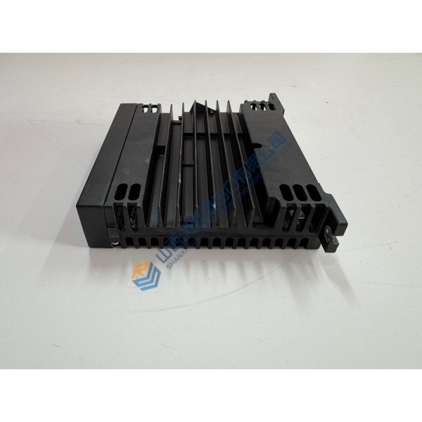
The SPERRY MARINE T65825812-7 is a 25 kW X-band modulator PCB assembly. It sits in the radar transceiver unit and generates the high-voltage pulse that drives the magnetron cathode.
Without this pulse, the radar transmits nothing. The board uses an SCR to resonantly charge a Pulse Forming Network (PFN) from -600 V to -1200 V, then discharges a -8 kV, 8 A negative pulse into the magnetron . Current production remains active — Northrop Grumman still receives DLA orders for this board .
Installation & Configuration Guide
Phase 1 — Pre-Installation (est. 15 min)
De-energize the radar transceiver unit at the main breaker. ❗ Wait 5 minutes — the PFN and high-voltage capacitors hold lethal charge. Verify zero voltage at the magnetron cathode with a Fluke 115 multimeter rated for 1 kV. Photograph all connector positions and the board’s mounting orientation.
Phase 2 — Removal (est. 5 min)
Label every cable going to the modulator board. Discharge the magnetron cathode to ground through a 10 kΩ, 25 W resistor before touching any high-voltage connection. Release the board mounting screws and pull straight out. Inspect the magnetron connection point for arcing marks.
Phase 3 — Installation (est. 10 min)
ESD wrist strap on, grounded to transceiver chassis. Verify the replacement board matches T65825812-7 exactly — different suffixes use different connector layouts. Seat the board and secure mounting screws. Reconnect cables per your photos. ❗ Do not wire from memory — the high-voltage section has no reverse-polarity protection.
Phase 4 — Power-On & Testing (est. 15 min)
Energize the transceiver. Observe the radar display for transmit status. Run a transmission test and verify magnetron current draw is within normal range. Check for arcing or corona at the high-voltage connections with the cabinet closed. Log the swap with date, part number, and radar system serial number.
Troubleshooting Quick-Reference:
- Radar powers up but no transmission → suspect modulator, interlock, or magnetron
- Radar trips on startup → do not cycle power; isolate overcurrent or shorted component
- Intermittent transmit → thermal-related failure or loose connector; monitor temperature rise
- ❗ Wrong revision installed → T65825812-7 differs from T65825812-3 and other suffixes in connector layout. Match the exact suffix.