Description
Product Introduction
Display screen flicker, touch unresponsiveness, or network packet dropouts on operator panels in chemical or pharmaceutical plants create major safety risks and obscure critical process alarms. The R. STAHL MT556 (MT-556-A-FX-TFT-PES) operator terminal resolves these hazardous area visualization issues by combining an explosion-proof, polyester-front enclosure with high-speed optical data communication.
Designed for installation directly in Zone 1, 2, 21, or 22 hazardous areas, this Series 500 Open HMI unit utilizes a multi-color TFT display and high-noise-immunity fiber-optic (FX) Ethernet interfaces. In my experience, dropping this rugged unit into a processing suite stops signal interference from nearby high-voltage drives and restores crisp, real-time process control.
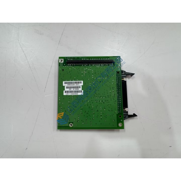
Installation & Configuration Guide
Phase 1 — Pre-Installation (est. 10 min): Isolate power feeds to the hazardous area enclosure and adhere strictly to local hot-work permit requirements. Wait 10 minutes for internal charge levels to dissipate. Gather a metric hex key set, fiber-optic cleaning kit, torque screwdriver, and a Fluke 115 multimeter. Photograph terminal wiring, fiber connections, and panel cutout gasket seating before removing the existing unit.
Phase 2 — Removal (est. 5 min): Disconnect the fiber-optic network cables carefully by releasing connector clips. Loosen power terminals and ground bonding straps. Unbolt the rear mounting clamps or perimeter panel screws, then ease the HMI unit forward out of the panel cutout. Inspect the cutout edge and IP sealing gasket for corrosion or physical damage.
Phase 3 — Installation (est. 10 min): Wear an anti-static wrist strap before opening the protective packaging. Check that the unit designation reads MT-556-A-FX-TFT-PES and verify hazardous area certification labels match zone requirements. Clean the fiber-optic cable ends using an optical cleaning cassette. Insert the terminal into the panel cutout, ensure the IP seal is seated flat, and tighten mounting clamps evenly to 0.8 N·m torque. Reconnect power and fiber lines per your initial photographs.
Phase 4 — Power-On & Testing (est. 15 min): Apply 24 V DC logic power and observe front screen boot routines (verify system diagnostics pass without optical link alarms). Connect to the host DCS or control system, verify touch/display calibration, and perform an end-to-end data transfer check. Monitor screen clarity and touch response during a 30-minute operational test run.
Troubleshooting Quick-Reference:
- No optical link signal → Clean fiber-optic transceivers; check fiber bend radius and ensure TX/RX channels are not reversed.
- Display fails to power up → Verify 24 V DC supply voltage stability under load using a calibrated multimeter.
- Touchscreen drift or no response → Execute hardware screen recalibration via system setup menu.
FAQ
Can I just drop this in and go? Not completely, because while the physical footprint may align with existing cutouts, you must configure network parameters, IP address settings, and system visualization project files to match your host DCS/PLC before bringing process loops live.
What does the “FX” and “PES” mean in the model code? Well, technically “FX” indicates a fiber-optic network interface for high-noise-immunity communication over long distances, while “PES” designates a polyester front panel construction built to withstand harsh chemical environments.