Description
Product Introduction
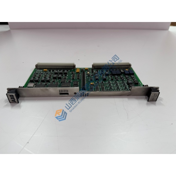
Need reliable analog data from HART transmitters in a Tricon CX safety system? The Triconex 3723X delivers exactly that. This TMR analog input module sits in the Tricon CX I/O expansion chassis and handles 32 single-ended channels at 0–5 VDC.
In field deployments of Tricon CX systems, the unit provides HART pass-through so you can query smart transmitters without extra multiplexers. Update rate sits at 50 ms. Accuracy holds under 1 % of full-scale range from –20 °C to 60 °C. Logic power stays below 11 W. Color code is yellow — easy visual ID in the rack.
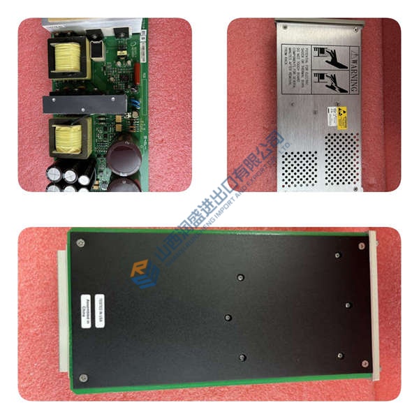
Installation & Configuration Guide
Phase 1 — Pre-Installation (est. 10 min)
De-energize the chassis and wait five minutes for residual discharge. Gather tools: ESD wrist strap, Fluke 115 multimeter, torque screwdriver, camera. Export the current TriStation configuration. Photograph every DIP switch, jumper, wire label, and rack layout. Verify the spare matches the exact part number.
Phase 2 — Removal (est. 5 min)
Label every wire before disconnection. Release the DIN-rail or chassis latch. Pull the module straight out, perpendicular to the backplane. Inspect connector pins for bent or corroded contacts. Set the old module aside for return or scrap.
Phase 3 — Installation (est. 10 min)
Strap on. Verify the part number on the new unit matches the configuration. Replicate DIP/jumper settings exactly from your photos. Seat the module until the latch clicks. Reconnect wiring at approximately 0.5 N·m. Run the pre-power checklist: correct slot, no bent pins, termination panels matched.
Phase 4 — Power-On & Testing (est. 15 min)
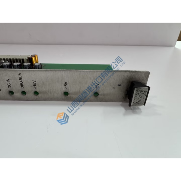
Apply 24 V DC (±10 %). Watch the LEDs: green = RUN, red flash = ERR, amber flash = DIAG. Connect programming software, download the program, and exercise every I/O point plus one full control loop. Confirm stable operation beyond 30 minutes. Log the swap in the maintenance record.
Troubleshooting quick-reference:
- No communications → check cable, switch port, and IP settings
- ERR steady → firmware mismatch; attempt controlled update
- Download fails → verify cable integrity and software version