Description
Product Introduction
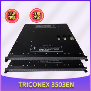
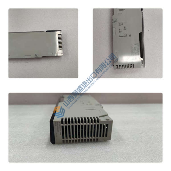
The Triconex CM3201 communication module links Tricon safety systems with distributed control hosts and supervisory human-machine interfaces. Occupying a single expansion slot in the main chassis, this module routes diagnostic data without disrupting triplicated execution loops. Bottom line — it works.
Isolating host query traffic from main processor buses prevents scan time degradation in safety instrumented functions. Featuring galvanic optical barriers across serial connectors, the board operates cleanly up to 19.2 kbps under industrial noise. Honestly, this complete physical separation between safety logic and external communications is actually clever for meeting strict IEC 61508 compliance.
Pricing & Availability Note: Listed pricing is for reference only; actual price depends on market conditions and batch volume. Request an official quote to verify current stock for the Triconex CM3201.
Installation & Configuration Guide
Phase 1 — Pre-Installation (est. 10 min)
- De-energize the host enclosure power circuit.
- Wait 5 minutes to discharge internal bus capacitors.
- Gather a flathead screwdriver, anti-static grounding strap, and Fluke 115 multimeter.
- Back up active TriStation 1131 safety projects and photograph rack slot assignments.
Phase 2 — Removal (est. 5 min)
- Loosen top and bottom retention screws on the faceplate.
- Disconnect serial cabling harnesses from DB9 communication ports.
- Pull the ejector levers outward to unseat the module from the backplane.
- Slide the unit straight out along rack guide rails to avoid pin damage.
Phase 3 — Installation (est. 10 min)
- Fasten an ESD wrist strap connected to a verified earth ground terminal.
- Verify the model tag on the side rail confirms a Triconex CM3201 before inserting.
- Replicate baud rate DIP switch configurations from pre-removal reference photos.
- Align module card edges with chassis guide slots and slide inward until latches lock.
- Torquing faceplate retention screws to ~0.5 N·m ensures proper frame grounding.
Phase 4 — Power-On & Testing (est. 15 min)
- Apply 24 V DC main supply power to the Tricon rack.
- Observe front panel LEDs during self-test (PASS LED should turn solid green).
- Connect TriStation diagnostic software via the front diagnostic port.
- Execute a loopback command across serial channels to confirm handshake status.
- Monitor operational data polling for 30 minutes to verify stable noise-free transmission.
Quality Verification SOP
In field deployments of critical safety systems, systematic component inspection prevents false trips and unexpected downtime. Every Triconex CM3201 undergoes strict physical and functional verification prior to dispatch:
- Incoming Inspection: We review OEM packing slips and customs import declarations for origin verification. Microscopic checks confirm circuit board trace integrity, checking for heat yellowing, solder reflow marks, or pin oxidation.
- Live Functional Test: Technicians install the unit into an active Tricon test rack. We perform full communication handshakes with TriStation software and external Modbus slave devices. Load testing runs continuously for >24 hours with temperature logging. A formal Test Report accompanies every module.
- Electrical Tests: Using a 500 V megohmmeter, we verify insulation resistance exceeding 10 MΩ between serial interface ports and backplane logic paths. Ground continuity is confirmed with a Fluke 115 multimeter across the housing bracket.
- Firmware Verification: Onboard firmware build numbers are read and logged in our system record. Rotary switch and jumper positions are photographed before final packaging.
- Final QC & Packaging: Upon technician sign-off, the card is wrapped in ESD shielding film, padded with high-density foam in a heavy-duty box, and sealed with a dated QC Passed seal.
(Note: Test photos and video logs are available on request. All units are confirmed functional after completing the steps above.)