
Description
Product Introduction
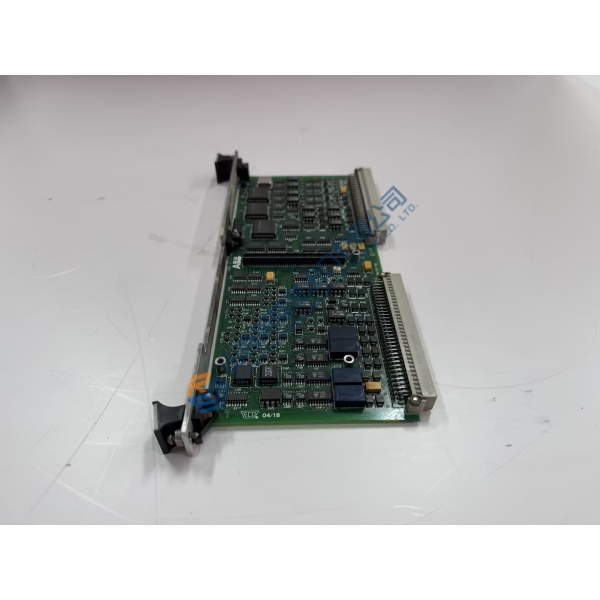
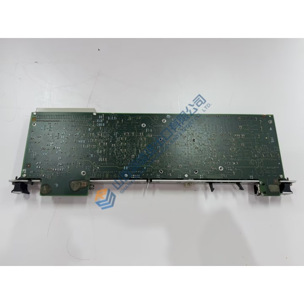
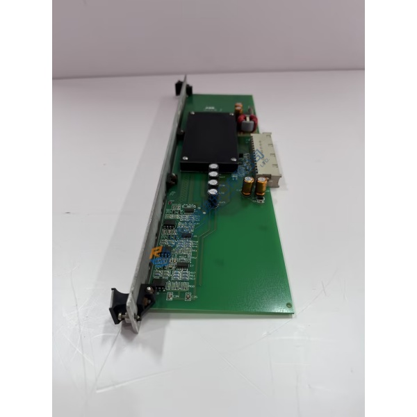
Instability in generator terminal voltage or phase firing drift in excitation systems frequently points to a degrading central control module. The UNITROL 6080A6T‑0/D3PD‑D400 ABB excitation controller card resolves field current fluctuations and switching delays by executing high-speed digital voltage regulation (AVR) algorithms across UNITROL 6000 static excitation cabinets. Designed for utility power plants and heavy industrial synchronous drives, this processor board manages tight field current regulation and thyristor bridge firing sequences under rapid load transients.
Field reports from power stations verify that replacing a faulting control board restores steady generator excitation within a ±0.1% tolerance margin. Installing a pre-tested controller unit clears nuisance field-overcurrent and loss-of-excitation alarms, ensuring continuous grid-synchronized operation. Honestly, running worn processor boards in high-capacity excitation systems is a risk that leads to unexpected generator trips and severe outage costs. This unit ships fully pre-tested from surplus warehouse stock, allowing plant engineers to clear system fault codes prior to scheduled maintenance turnarounds.
Key Technical Specifications
- Parameter: Value
- Part Number: 6080A6T‑0/D3PD‑D400
- Hardware System: UNITROL 6000 Series
- Manufacturer: ABB
- System Family: Static Excitation Systems (SES) / Automatic Voltage Regulators (AVR)
- Module Type: Main Processing & Thyristor Driver Control Board
- Auxiliary Logic Voltage: 24 V DC (18 to 30 V DC operational range)
- Signal Interfaces: High-speed fiber-optic gate channels and bus communications
- Operating Temperature: −10 to +60 °C (14 to 140 °F)
- Mounting Style: Enclosure chassis rack slot mount
- Isolation Rating: Full galvanic/optical isolation between logic circuits and power thyristor bridge
- Conformal Coating: Heavy-duty environmental coating for power station environments
Installation & Configuration Guide
Phase 1 — Pre-Installation (est. 10 min) De-energize the main excitation cabinet circuit breaker and auxiliary power feeds completely. Wait 15 minutes for high-voltage DC field link capacitors and field suppression circuits to discharge safely below 50 V DC. Gather an ESD grounding wrist strap, insulated hand tools, and a digital multimeter. Save existing AVR parameter files using ABB CMT6000 service software. Photograph all fiber-optic channels, terminal plugs, and onboard jumper settings before touching the original card.
Phase 2 — Removal (est. 5 min) Disconnect optical channels carefully by depressing their connector release tabs. Mark all terminal plugs before pulling them from the board header sockets. Unfasten retaining screws located at the module faceplate corners. Slide the card straight out along its cabinet guide tracks to avoid bending rear edge connectors against adjacent framing.
Phase 3 — Installation (est. 10 min) Put on your grounded ESD wrist strap before handling replacement hardware. Confirm the UNITROL 6080A6T‑0/D3PD‑D400 part number printed on the circuit board silk layer. Set onboard DIP switches and jumpers to match your pre-installation reference photos. Align the board with its rack guides, slide it inward smoothly until edge connectors lock into the backplane, and torque faceplate screws to 0.5 N·m before re-plugging optical channels.
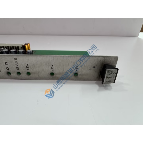
Phase 4 — Power-On & Testing (est. 15 min) Apply 24 V DC auxiliary power to the control rack without energizing generator field power. Observe diagnostic LEDs: green power indicators must remain lit, while red fault indicators should extinguish post-self-test. Connect your workstation running CMT6000 software, download project configuration files, and perform a low-power thyristor gate firing test. Keep the unit under continuous monitoring for 30 minutes to confirm firing pulse stability before returning the generator to service.



