Description
Product Introduction
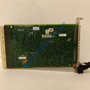
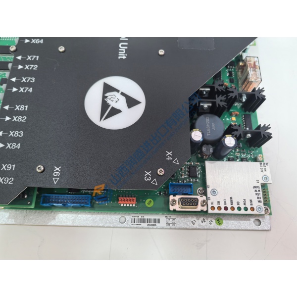
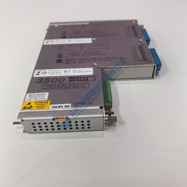
GE VMIVME-7750-734000 is a 6U, single-slot VMEbus computer for embedded control, process monitoring, test equipment, instrumentation, and legacy turbine-control platforms. The related GE internal code is 350-027750-734000E.
Built around Intel’s 815E chipset, the VMIVME-7750 platform combines Pentium III processing, dual 10/100Base-T Ethernet, a PCI-to-VME bridge, IDE or CompactFlash storage, serial ports, USB, SVGA, watchdog, and one PMC expansion site. Confirm the suffix-specific processor and memory before ordering.
The VMIVME-7750 manual identifies the board as a passively cooled Pentium III VME computer using the Intel 815E chipset and a transparent PCI-to-VME bridge. It also documents dual Ethernet, 512 MB maximum PC133 SDRAM, one PMC site, and VME Rev. C.1 compliance.artisantg+1
The exact 734000E configuration remains important. Public ordering information separates processor, SDRAM, CompactFlash, and temperature options by code. Verify the installed CPU, RAM, flash, BIOS, and temperature grade from the board label or configuration printout.
Installation & Configuration Guide
Phase 1—Pre-Installation — estimated 20 minutes
Shut down the VME chassis and connected control equipment. Remove backplane power and wait at least 5 minutes for discharge before handling the board.
Prepare:
- ESD wrist strap and grounded ESD mat.
- Fluke 115 multimeter.
- Insulated screwdriver set.
- VME board-extraction tool.
- Console cable for RS-232 access.
- Boot media or CompactFlash backup.
- Operating-system image and driver archive.
- VME memory-map and slot-configuration records.
- Camera for jumpers, cables, and front-panel settings.
Back up the operating system, application files, BIOS settings, VME address map, interrupt assignments, driver versions, and CompactFlash contents. Record whether the board acts as the VME system controller or as a peripheral CPU.
Photograph the board label, CPU and memory markings, PMC card, jumper positions, Ethernet cables, serial adapters, VME slot, and rear transition connections.
Phase 2—Removal — estimated 10 minutes
Label all Ethernet, serial, USB, video, keyboard, mouse, IDE, and rear-I/O cables before disconnection. Record the board’s exact slot and system-controller position.
Release the VME retainers and pull the board straight from the backplane. Do not remove or install the board while power remains applied.
Inspect P1 and P2 connectors for bent pins, contamination, oxidation, and heat damage. Check the chassis backplane before installing the replacement. The manual specifically warns against board removal or installation with power applied.
Phase 3—Installation — estimated 15 minutes
Apply ESD protection before opening the replacement package. Verify the VMIVME-7750-734000 label, 350-027750-734000E code, processor option, memory, CompactFlash option, PMC card, and temperature grade.
Insert the board straight into the documented VME slot. Secure both front-panel retainers. Install the PMC card only after confirming the card uses the supported 5 V PMC interface and mechanical clearance.