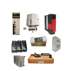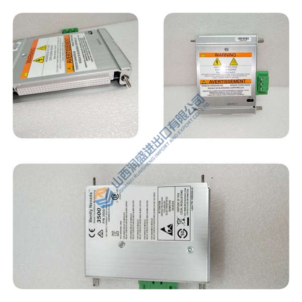
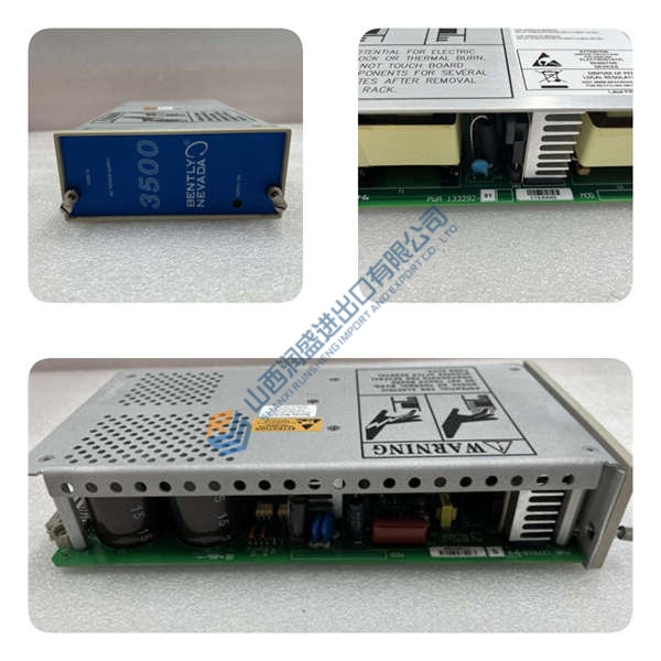
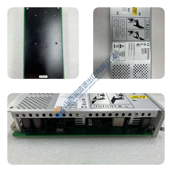
Description
Product Introduction
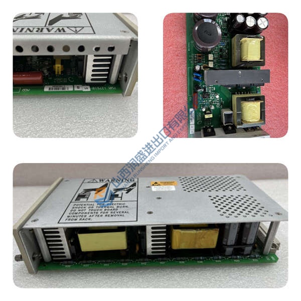
The Woodward BL20-400 is a 3-phase DC power supply and battery charging unit designed for continuous operation in industrial power systems, turbine controls, and emergency DC supply applications. It handles both 12 V and 24 V lead-acid or NiCd batteries while simultaneously feeding DC loads in parallel.
In field deployments of SEG/BL20 systems, this unit stands out for its wide 340–530 V AC input range and switchable 12/24 V output with ±2% voltage tolerance. The 620 W continuous rating (derated to 350 W at 70 °C) gives it enough headroom for engine start transients without tripping. If you’re replacing an older SEG BL20400, this is the direct OEM equivalent—same terminal layout, same DIN-rail footprint.
Installation & Configuration Guide
Phase 1—Pre-Installation (est. 10 min)
De-energize the 3-phase supply and wait 5 min for capacitor discharge. Grab a Torx T20, wire strippers, and a Fluke 115 multimeter. Export your existing charger settings if you have a historian; photograph the old unit’s terminal wiring, DIP switches, and rack position.
Phase 2—Removal (est. 5 min)
Label every wire before disconnecting—trust me, you’ll thank yourself later. Release the DIN-rail latch, pull the module straight out perpendicular to the backplane, and inspect the backplane pins for bent contacts or corrosion.
Phase 3—Installation (est. 10 min)
Strap on your ESD wristband. Verify the part number matches BL20-400 (not BL20-200 or BL20-100). Replicate the DIP switch settings from your photos—12 V/24 V mode, Pb/NiCd selection. Seat the unit until the latch clicks, torque terminal screws to ~0.5 N·m, then run a pre-power checklist: input L1/L2/L3 continuity, output +/− polarity, ground bond.
Phase 4—Power-On & Testing (est. 15 min)
Verify input voltage is 3×340–530 V AC (±10%). Power up and watch the LEDs: green = RUN, red flash = ERR, amber flash = DIAG. Hook up your programming tool or DCS, confirm the normalized voltage/current signals (10–50 V, 10–25 A) are sane, then run a full I/O loop test. Log at least 30 min of stable operation before signing off.