Description
Product Introduction
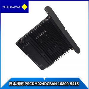
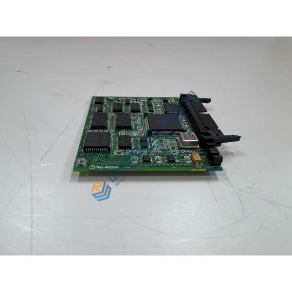
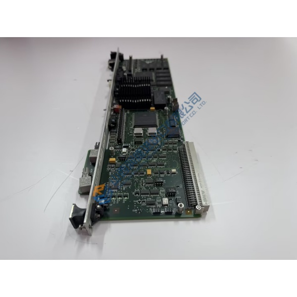
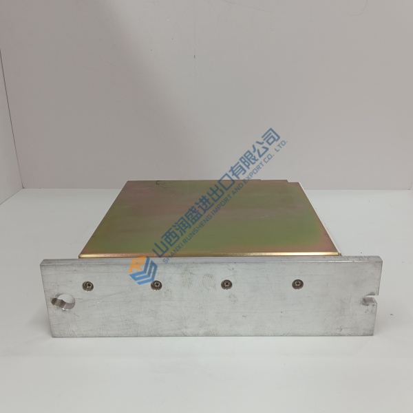
Yokogawa CP-451 C2K20006H is the central processor module for the Field Control Station in CENTUM VP and CS 3000 distributed control systems. It executes regulatory and sequential control logic, manages I/O scanning, and handles high-speed communication over the Vnet/IP control network.
In dual-redundant Pair & Spare configuration the two CPUs run identical logic in parallel. A hardware comparator detects any mismatch and transfers control without interruption. This design keeps critical loops online during a processor fault. The module seats in the standard FCS chassis and draws power from the system backplane.
Installation & Configuration Guide
Phase 1 — Pre-Installation (est. 10 min)
De-energize the FCS rack and wait 5 min for residual discharge. Tools required: ESD wrist strap, multimeter (Fluke 115), torque screwdriver. Export the current project and photograph DIP-switch settings, station address and backplane connectors.
Phase 2 — Removal (est. 5 min)
Label every cable. Release the module latch. Withdraw the board straight out of the chassis; inspect connector pins for damage or corrosion.
Phase 3 — Installation (est. 10 min)
Apply ESD protection first. Verify the full part number CP-451 C2K20006H on the nameplate. Set DIP switches to match the original station address and start mode (photograph first). Seat the module firmly until the latch engages. Reconnect any external cables and complete the pre-power checklist.
Phase 4 — Power-On & Testing (est. 15 min)
Apply system power and observe status LEDs. Use the engineering station to confirm module recognition, download the control database if required, and verify dual-CPU synchronization. Run a functional test of critical loops and communication for >30 min. Log the module change in the maintenance record.
Troubleshooting quick-reference:
- No communications → check Vnet/IP cabling, station address DIP switches and firmware revision
- FAIL LED steady → processor mismatch or hardware fault; verify Pair & Spare partner
- Download fails → confirm engineering software version and project compatibility