Product Core Brief
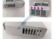
• Model: ILX56-MM • Brand: ProSoft Technology • Series: ControlLogix Platform (Allen-Bradley) • Core Function: Enables dual-port Modbus Master/Slave serial communication within ControlLogix rack architectures. • Product Type: In-Rack Modbus Serial Communication Module • Key Specs: Dual RS-232/RS-422/RS-485 ports | 2500 V isolation | Modbus RTU/ASCII • Condition: New Original (New Surplus)
Product Introduction
ProSoft ILX56-MM is a single-slot, dual-port Modbus serial communication module built for Allen-Bradley ControlLogix control systems. The module acts as an in-rack interface, allowing a ControlLogix CPU to exchange data with field devices like variable frequency drives, power meters, flowmeters, and legacy PLCs without external gateways.
This unit supports independent Modbus Master or Slave configuration on each serial port using RS-232, RS-422, or RS-485 electrical standards. Installing this module ensures low-latency backplane data transfers to the processor while protecting system electronics via 2500 V optical port isolation.
Quality Control & Testing Process
- Inbound Inspection: Trace origin documentation against packing lists. Check anti-counterfeit labels, verify serial numbers, and inspect gold backplane edge connectors for corrosion, scratches, or missing pins.
- Live Functional Testing: Slot the module into a ControlLogix 1756 chassis with an active CPU. Perform power-on self-test (POST), establish serial handshakes using Modbus RTU master/slave loopback test benches, perform full-scale I/O data table mapping tests, and run continuous load testing for >24 hours.
- Electrical Testing: Check optical port isolation and supply rail insulation resistance using a 500 V Megger to verify readings exceed 10 MΩ. Test grounding continuity across chassis ground contacts.
- Firmware Verification: Read and record the exact module firmware version via ProSoft Configuration Builder (PCB). Archive existing configuration files and DIP switch settings before repacking.
- Final QC & Packaging: Enclose the unit in an anti-static shielding bag. Wrap securely in dense industrial bubble wrap, seal inside a reinforced shipping container, and apply a QC Passed verification label.
Technical Pitfall & Installation Guide
• Firmware Rev Mismatch: Replacing this module with a different firmware version can cause profile errors in Studio 5000 / RSLogix 5000 or break Add-On Instruction (AOI) communications. Always check and match the firmware version before installing the replacement. • DIP Switch/Jumper Errors: Incorrect RS-232/RS-485 hardware jumper settings or missing termination resistors on RS-485 networks will result in framing errors or dropped packets. Photograph and replicate the jumper layout of the old module before installation. • Terminal/Wiring Incompatibility: Verify pinout diagrams for RS-232 vs RS-485 connections on the removable terminal block. Swapping transmit/receive pairs or miswiring signal ground will prevent serial communication. • Power Supply Constraints: High current draw on the 5.1 V DC backplane rail (800 mA) can overload under-sized 1756 power supplies. Confirm that your rack power supply maintains at least a 20% power margin. • ESD Protection: Static discharges can ruin sensitive serial line transceivers. Always wear a grounded anti-static wrist strap when handling or seating the module into the 1756 backplane.