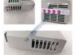
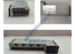
Product Core Brief
• Model: 8237-1246 • Brand: Woodward • Series: 2301E Series Digital Control • Core Function: Manages load sharing and speed control for diesel engines, gas engines, or steam turbines driving generators or pumps. • Product Type: Digital Load Sharing & Speed Controller Engine • Key Specs: 24 V DC input | 4-20 mA / 0-200 mA actuator driver | Modbus RTU communications • Condition: New Original (New Surplus)
Product Introduction
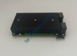
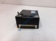
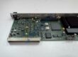
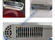
Woodward 8237-1246 is a digital speed and load sharing control module engineered for prime movers driving electrical generators or mechanical loads. The controller manages start sequencing, speed governing, generator load distribution, and deceleration profiles across industrial power generation platforms.
This unit incorporates flexible software configuration options via software interface tools alongside dedicated analog and discrete I/O channels. Installing this module ensures low-drift speed control and maintains backward-compatible mounting footprints when replacing legacy analog 2301A control systems.
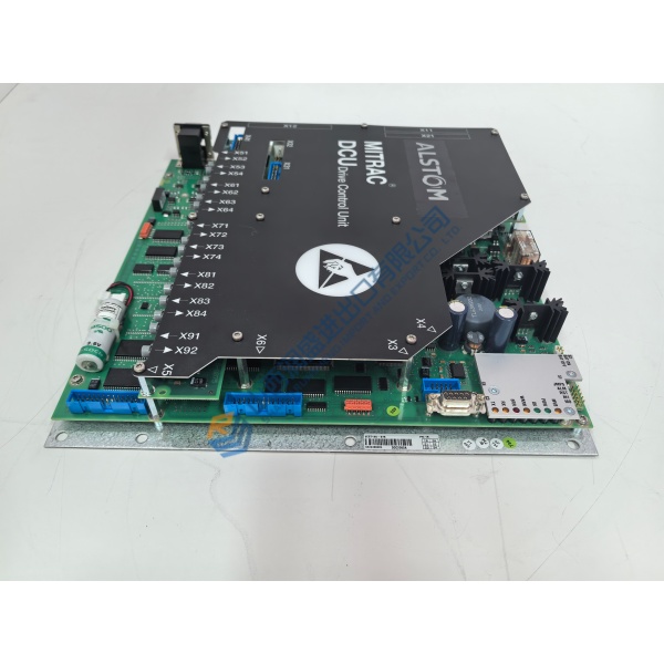
Quality Control & Testing Process
- Inbound Inspection: Trace origin documentation against customs and shipping manifests. Inspect serial number labels, check metal enclosure surfaces for physical scratches, and verify all terminal strip screws are present and uncorroded.
- Live Functional Testing: Mount the controller to a specialized Woodward simulator workbench. Perform power-on self-test (POST), inject frequency signals to simulate MPU speed feedback, measure analog actuator output curves, test Modbus serial data transfers, and conduct load testing for >24 hours.
- Electrical Testing: Perform line-to-ground insulation resistance testing using a 500 V Megger to verify readings exceed 10 MΩ. Test terminal block ground continuity across chassis grounding points.
- Firmware Verification: Read and record onboard firmware rev numbers using Control Assistant software. Back up factory calibration maps and archive configuration files before repacking.
- Final QC & Packaging: Enclose the unit inside anti-static shielding bags. Cushion thoroughly with industrial bubble wrap inside a heavy-duty container and apply a QC Passed verification label.
Technical Pitfall & Installation Guide
• Firmware Rev Mismatch: Uploading an incompatible .sid configuration file or mismatching software application versions can cause boot errors or reset tuning constants. Always archive existing parameter files prior to replacing hardware. • DIP Switch/Jumper Errors: Misconfiguring the actuator output range jumpers (4-20 mA vs 0-200 mA) will result in unexpected valve travel or failure to open fuel racks. Photograph and replicate the jumper positions of the old unit before installation. • Terminal/Wiring Incompatibility: Connecting AC lines or unshielded speed cables will introduce high-frequency electrical noise, resulting in engine speed hunting or erratic governor response. Route signal wiring in dedicated grounded conduit. • Power Supply Constraints: Voltage dips on the 24 V DC supply below 18 V DC during engine cranking can cause processor resets. Ensure the supply battery bank maintains at least a 20% power margin under full load. • ESD Protection: Static charges can ruin delicate analog signal conditioning circuits. Always wear a grounded anti-static wrist strap when wiring terminals or attaching communication cables.