Product Core Brief
- Model: 8440-2051
- Brand: Woodward
- Series: easYgen-3000 / easYgen-3200 P2
- Core Function: Controls, protects, and synchronizes multiple generator sets
- Type: Genset Controller with built-in HMI
- Key Specs: Up to 32 units; load sharing; color LCD; 12/24 VDC
- Condition: New Original (New Surplus) — not refurbished
Product Introduction
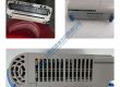
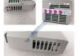
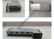
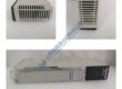
WOODWARD 8440-2051 is the easYgen-3200 P2 genset controller from the easYgen-3000 series. It manages single or multi-unit generator operation with load-dependent start/stop and isochronous load sharing for up to 32 sets.
The unit includes a color LCD operator interface with soft keys and supports engine, generator, and mains protection. Four operating modes, breaker control logic, and three freely configurable PID loops give the flexibility needed for both standby and prime-power applications. Front-panel mounting and wide-range 12/24 VDC supply keep installation straightforward.
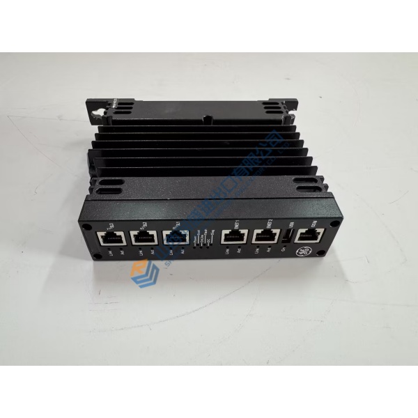
Confirm exact firmware version and I/O configuration against your application drawings and the Woodward easYgen-3000 manual. Specs reflect series documentation; always verify with the OEM datasheet.
Installation & Configuration Guide
Phase 1 — Pre-Installation (est. 10 min)
De-energize the control panel and wait a full 5 minutes for residual voltage to drop. Tools required: Fluke 115 multimeter, ESD wrist strap, torque driver, camera. Back up the existing configuration if the unit still powers. Photograph every terminal, CT connection, and communication cable before removal.
Phase 2 — Removal (est. 5 min)
Label every wire and connector. Release the front-panel mounting hardware. Pull the controller straight out. Inspect the panel cut-out and terminal blocks for damage.
Phase 3 — Installation (est. 10 min)
Attach the ESD strap. Confirm the part number matches 8440-2051. Seat the unit in the panel cut-out and secure the mounting. Reconnect power, CTs, voltage sensing, and communication cables. Run a pre-power checklist: correct DC supply present, polarity correct, no shorts.
Phase 4 — Power-On & Testing (est. 15 min)
Apply 12/24 VDC and verify the color display boots cleanly. Load or verify the configuration. Check voltage and current readings against known values. Exercise start/stop, breaker control, and load-share functions if multiple units are present. Confirm stable operation for at least 30 minutes. Log the swap in the maintenance record. Test photos or video available on request.
Troubleshooting quick-reference:
- No display → check DC supply voltage and polarity
- Incorrect readings → verify CT ratio and voltage sensing connections
- Load-share failure → confirm communication network and unit addressing