
Description
Product Introduction
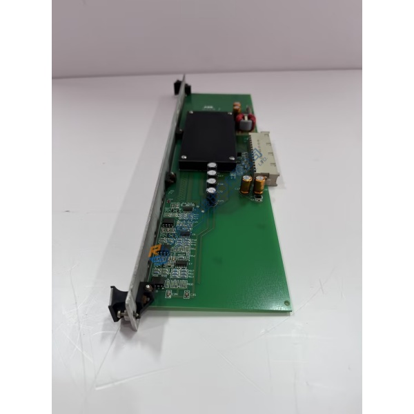
Failed excitation drive controllers often cause sudden generator trips during utility load shedding. The 3BHE014023R0101 UFC789AE101 ABB control board resolves this processing vulnerability by executing high-speed control loops for synchronous motor drives and generator excitation units. Designed for ABB heavy-industrial drive cabinets, this processing unit processes system feedback inputs directly to adjust thyristor firing angles, maintaining steady DC output voltage within a tight ±0.1% margin under heavy line fluctuation.
In-field power generation applications demonstrate that clean optical transmission keeps signal execution delays well under 1 ms. Swapping out a degraded processing unit restores stable field current regulation immediately on large synchronous machines. To be frank, keeping aged control cards in critical excitation systems invites costly downtime when thermal cycling cracks fine circuit traces. This unit ships fully pre-tested from clean warehouse stock, letting site engineers resolve controller faults before scheduled plant restarts.
Key Technical Specifications
- Parameter: Value
- Part Number: 3BHE014023R0101
- Hardware Code: UFC789AE101
- Manufacturer: ABB
- Control System: UNITROL / MEGAPACK Systems
- Module Type: Main Controller Board / Processor Card
- Logic Voltage: 24 V DC (18 to 30 V DC range)
- Optical Interfaces: Fiber-optic I/O channels for noise-free pulse triggering
- Operating Temperature: −10 to +65 °C (14 to 149 °F)
- Mounting Type: Integrated subrack panel slot mount
- Isolation Rating: Optical isolation between control logic and power stage
- Conformal Coating: Class 3C2 industrial environment protection standard
Installation & Configuration Guide
Phase 1 — Pre-Installation (est. 10 min) De-energize the drive cabinet main circuit breaker completely. Wait 5 minutes for internal DC link capacitors to discharge below 50 V DC. Gather an insulated screwdriver set, ESD grounding strap, and multimeter. Save system parameters from your control panel workstation. Photograph all wire locations, optical cable routes, and onboard jumper configurations on the board before removal.
Phase 2 — Removal (est. 5 min) Disconnect fiber-optic connectors carefully by pressing their release tabs. Mark all copper terminal plugs before pulling them from the board header. Unfasten retaining screws located at the module corners. Slide the card straight out from its slot guides, making sure not to bend or catch backplane pins against adjacent chassis parts.
Phase 3 — Installation (est. 10 min) Wear your connected ESD wrist strap at all times. Check the 3BHE014023R0101 UFC789AE101 part number printed on the circuit board silk layer. Set onboard jumpers to match your reference pictures precisely. Position the card into its rack guides, push firmly until the rear bus sockets connect, and tighten mounting screws to 0.5 N·m before re-plugging optical channels.
Phase 4 — Power-On & Testing (est. 15 min) Supply 24 V DC logic power to the cabinet rack. Check diagnostic status LEDs: green power indicators must remain lit, while fault indicators should clear after system self-check. Connect your configuration computer, load drive parameter files, and trigger a low-power pulse test on the converter bridge. Keep the unit running for 30 minutes under monitoring to verify signal stability before returning the drive to service.
Troubleshooting Quick-Reference
- No Communication / Bus LED Off: Check optical cable bend radius. Inspect fiber ends for dust using an optical scope. Confirm logic supply voltage.
- Converter Fault Active: Check onboard jumper selections. Measure incoming power lines using a Fluke 115 multimeter to confirm clean logic rails.
- Pulse Trigger Errors: Inspect optical transceivers for proper latching. Re-verify parameter settings inside control software.



