

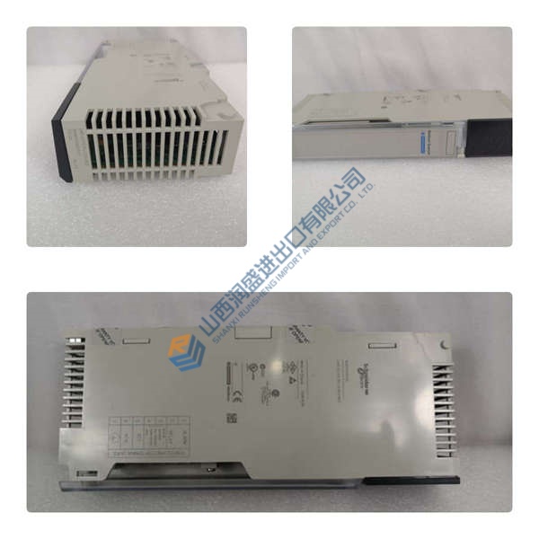
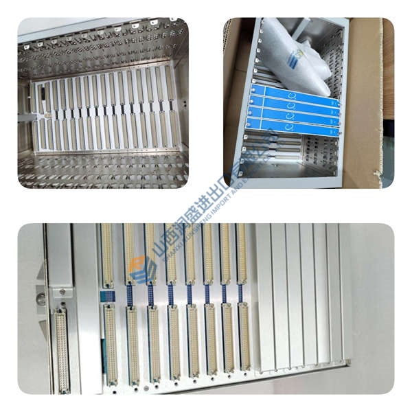
Description
Product Introduction
ABB SYN5202-0277 delivers high-precision automatic synchronization and synchrocheck supervision within power generation facilities and utility substations. Designed for synchronous generators, islanded microgrids, and grid tie-breakers, this module continuously measures phase angle deviation ($\Delta\phi$), slip frequency ($\Delta f$), and voltage difference ($\Delta V$) between generator terminals and live busbars. Operating on dual microprocessor channels, it issues precise breaker closure signals at the exact moment of phase coincidence to avoid high mechanical torque shocks and electrical grid disturbances. In field deployments of AC800M systems, fast and reliable synchronizing logic prevents out-of-phase closure events that could catastrophically damage generator shafts.
Replacing legacy synchronizing hardware during critical turnaround windows presents serious operational hazards. Fitting standard panel rack cutouts or subrack frames, the unit drops directly into existing protection schemes without necessitating full cabinet re-wiring or CT/PT transducer replacements. Is this design choice actually clever? Absolutely, because independent hardware lockouts block closure commands if frequency slip or voltage differentials exceed strict safety thresholds, regardless of main controller commands. Listed pricing serves as reference only; actual market pricing depends on global inventory levels. Contact our procurement desk today to request a formal quote for current stock.
Quality Inspection and Verification SOP
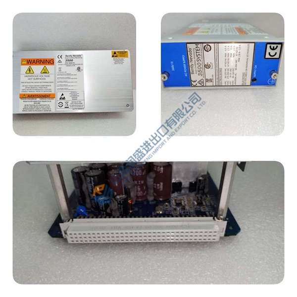
In our testing facility, every incoming synchronizing module undergoes meticulous multi-point verification before entering warehouse stock. We verify source documentation against OEM packing manifests and customs paperwork. Technicians perform anti-counterfeit checks, examining laser markings, chassis batch codes, and terminal strip integrity. Physical checks confirm zero backplane pin bending, housing cracks, or screw terminal thread damage.
Live functional testing begins by mounting the ABB SYN5202-0277 on a test rack and applying auxiliary control power while monitoring voltage stability with a Fluke 115 multimeter. Observing startup LED diagnostics, we feed dual 110 V AC secondary signals from dual-channel precision AC signal generators into the generator and busbar voltage sensing terminals. Technicians sweep phase angles from -180° to +180° and alter frequency slip rates, capturing exact breaker closure relay contact timing on a digital storage oscilloscope during a 24-hour continuous load test. Insulation resistance is verified using a 500 V megohmmeter to ensure voltage input-to-ground isolation exceeds 10 MΩ. Hardware jumper settings and firmware parameters are logged and photographed for customer records. Following technician sign-off, the unit is sealed in anti-static packaging and boxed with custom foam blocking. Test photos and raw video recordings remain available on request. Units are confirmed functional after completing all tests above.
Technical Pitfall Guide for Integration Engineers
Having supported dozens of power generation retrofits, our engineering team highlights five critical mistakes that stall installations.
- Inverted PT Voltage Polarity Wiring: Wiring phase-to-neutral or secondary potential transformer leads in reverse polarity creates an artificial 180° phase shift. When the actual system is synchronized, the relay perceives a out-of-phase condition and locks out — or worse, commands closure into a dead short. Verify PT voltage phasing with a phase rotation meter prior to energization.
- Breaker Closing Time Compensation Misconfiguration: Setting internal breaker close signal lead times to zero fails to account for mechanical circuit breaker operating times (typically 40 to 80 ms). The close signal arrives after zero phase crossing, closing the breaker out of phase. Measure total breaker mechanical operating time and program matching anticipatory lead time into the unit.
- Missing Cabinet Earth Grounding: Omitting a dedicated chassis earth connection allows ground loops and electromagnetic switching noise to disrupt sensitive analog zero-crossing detection circuits. Bolt a heavy copper earth strap directly from the chassis grounding terminal to the main panel earth bar.
- Incorrect PT Ratio Scaling Parameters: Setting potential transformer transformation ratios incorrectly in software/jumpers causes false $\Delta V$ voltage lockout alarms, preventing synchronization even when generator and grid voltages match. Double-check primary and secondary PT voltage specifications before testing.
- Electrostatic Discharge (ESD) During Terminal Wiring: Handling terminal blocks and internal setting dip switches without grounding accessories risks damaging sensitive CMOS signal-conditioning microchips — though your mileage may vary depending on ambient humidity. I watched an engineer skip the strap in January. The module smoked on power-up. $2,000 gone. Always wear an ESD wrist strap connected to cabinet earth ground.
Keep these five points in mind and you’ll cut 90% of your rework time.
Installation & Configuration Guide
Phase 1 — Pre-Installation (Estimated Time: 10 minutes)
De-energize main control power supplies and lock out generator PT and busbar PT voltage input breakers. Wait 5 minutes for internal power supply capacitors to discharge completely. Gather a 3 mm slotted screwdriver, phase rotation meter, ESD grounding wrist strap, and calibrated AC signal generator. Export configuration parameters and relay settings from engineering documentation. Photograph original panel cutout positioning, terminal wiring layouts, and hardware DIP switch/jumper configurations.
Phase 2 — Removal (Estimated Time: 5 minutes)
Tag every PT voltage wire, auxiliary power lead, and relay output cable before detachment. Unthread terminal screws and carefully pull connector plugs or wire pairs away from the rear housing. Loosen panel mounting clamps or subrack retaining screws. Slide the old module straight forward out of the mounting cutout. Inspect rear terminal blocks and rack guides for dust or physical damage.
Phase 3 — Installation (Estimated Time: 10 minutes)
Put on a grounded anti-static wrist strap before opening the protective packaging of the ABB SYN5202-0277. Replicate DIP switch and hardware jumper settings matching your pre-installation reference photos. Slide the module into the panel cutout or subrack frame until flush. Tighten side mounting clamps or front panel retaining screws to 0.8 N·m. Reattach terminal wiring blocks to designated rear ports according to marked wire tags.
Phase 4 — Power-On & Testing (Estimated Time: 15 minutes)
Verify incoming auxiliary power voltage reads within nominal limits using a multimeter before powering on the unit. Apply auxiliary power and observe front panel status indicators. A steady green READY LED indicates proper module startup; a red FAULT LED indicates an internal self-test failure or PT signal loss. Inject synchronized 110 V AC test signals into $V_{GEN}$ and $V_{BUS}$ terminals, verify $0^\circ$ phase difference display, and confirm closure relay contact operation. Monitor stable system performance for at least 30 minutes before logging the hardware replacement in plant maintenance records.



