Description
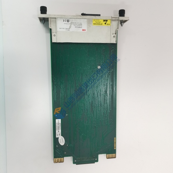
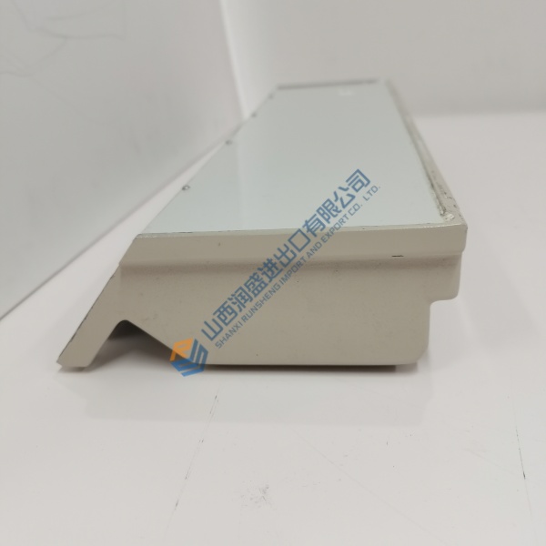
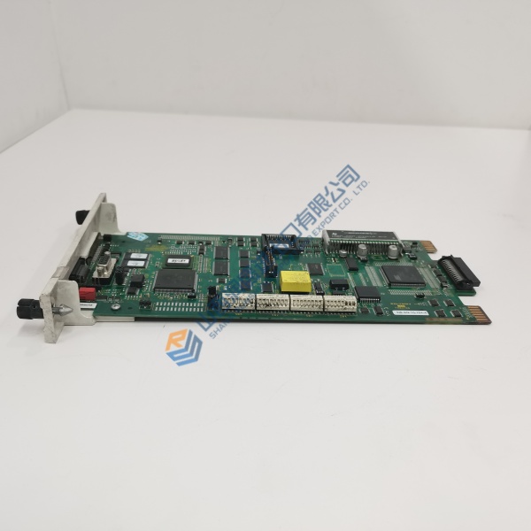
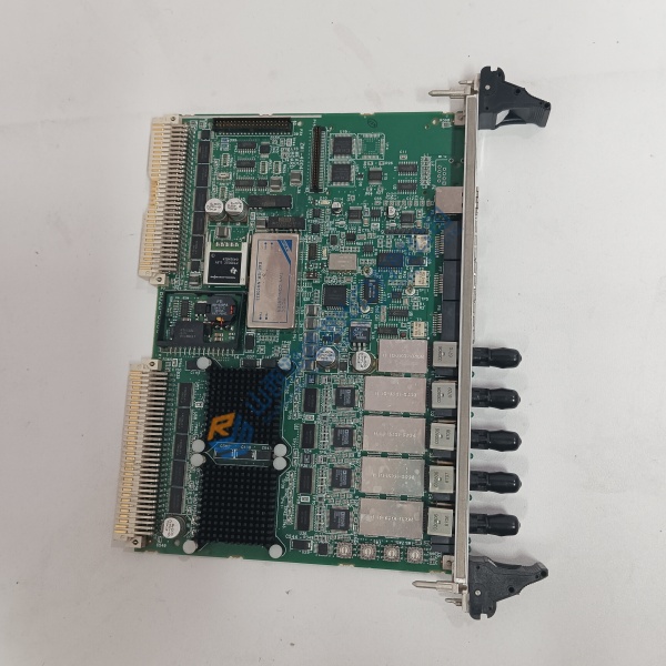
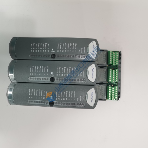
Product Introduction Integrating the Bently Nevada 288055-01+146031-01 transient data interface assembly into a 3500 series machinery protection rack establishes a reliable bridge for continuous vibration telemetry. Comprising the main 288055-01 processing card and the rear 146031-01 Ethernet I/O card, this module pair aggregates high-speed waveform data without overburdening host monitoring networks.
Procurement teams specify this exact 3500/22M combination when replacing obsolete 3500/20 rack interface cards during critical plant turnarounds. It delivers high-speed trend capturing across 100Base-TX links, operating reliably within harsh enclosure temperatures ranging from -30 °C to +65 °C.
Installation & Configuration Guide Phase 1 — Pre-Installation (est. 10 min) De-energize the 3500 rack power supplies completely. Wait 5 minutes for bus discharge before touching internal assemblies. Prepare a Fluke 115 multimeter, flathead screwdriver, and static-grounding wrist strap. Export your current rack configuration file in the 3500 Rack Configuration Software, then photograph existing DIP switch banks, Ethernet cable routes, and backplane slot positions.
Phase 2 — Removal (est. 5 min) Label the RJ-45 network cables before unplugging them from the rear I/O card. Loosen the top and bottom captive screws on the existing front 3500/20 or 3500/22M card. Pull the module straight forward out of slot 1. Undo the rear captive screws and extract the old rear I/O card. Inspect slot 1 backplane pins for misalignment or dust buildup.
Phase 3 — Installation (est. 10 min) Put on your ESD wrist strap prior to handling the sealed static bags. Confirm the front module part number reads 288055-01 and the rear card reads 146031-01. Set the DIP switches on the new main card to match your reference photos exactly. Insert the rear I/O card into the upper-rear slot 1 and tighten its screws to 0.5 N·m. Slide the front main module into the front slot 1 guide rails until seated, securing its faceplate screws. Plug in the labeled network patch cables.
Phase 4 — Power-On & Testing (est. 15 min) Verify incoming rack power supply voltage reads 24 V DC ±10% or 120/240 V AC depending on your rack supply configuration. Apply power to the rack. Observe front LEDs: the OK light must shine steady green, while TX/RX blinks during network traffic. Connect your laptop via the front USB port, upload the configuration, re-verify IP settings, and initiate a System 1 handshake. Run a full 30-minute operational test before logging the swap in your plant maintenance database.
Troubleshooting Quick-Reference
- No comms → check IP subnet settings, Ethernet patch cord pinout, and switch port link LEDs
- ERR / OK off → firmware mismatch between TDI and rack monitor cards; execute a firmware push
- System 1 connection drop → verify 146031-01 link speed settings match your plant switch configuration