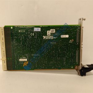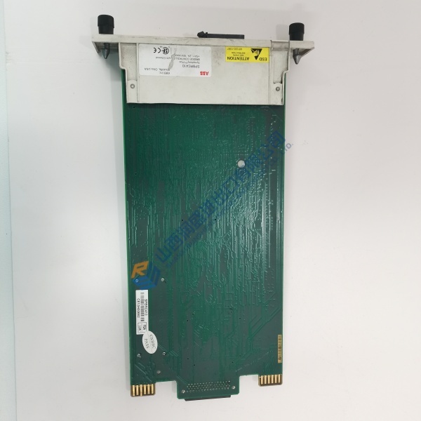
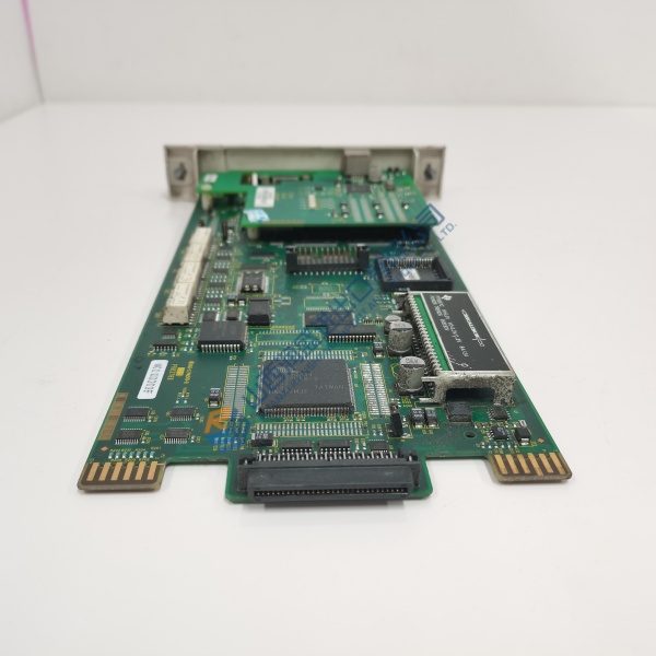
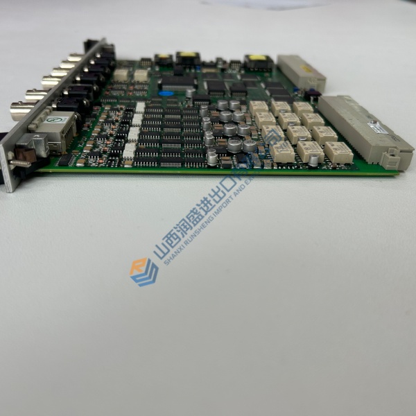
Description
Product Introduction Deploying the GE H201TI thermocouple input board into an active turbine control rack ensures steady signal acquisition from high-temperature exhaust and bearing sensors. Designed for critical turbomachinery protection, this unit conditions raw millivolt signals across 8 isolated channels to prevent control drift in heavy-duty industrial environments.
Engineers routinely select this interface card to replace aging I/O units during planned turnarounds. It delivers a fast scan time under 5 ms per channel, maintaining precise thermal monitoring across operating limits of 0 to 60 °C.
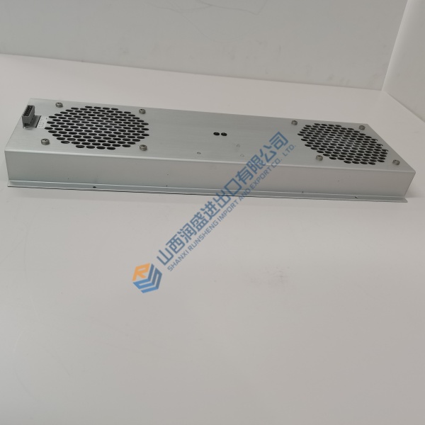
Installation & Configuration Guide Phase 1 — Pre-Installation (est. 10 min) De-energize the enclosure completely. Wait 5 minutes for full capacitor discharge before opening the bay doors. Gather a Fluke 115 multimeter, a #2 Phillips screwdriver, and an anti-static wrist strap. Export the current system software project, then photograph all terminal wiring connections, cable routing, and existing board jumper positions.
Phase 2 — Removal (est. 5 min) Tag every terminal block wire using printed labels before unscrewing. Unlatch the retaining screws on the top and bottom of the card faceplate. Pull the module straight out perpendicular to the rack backplane to avoid bending the rear pin connectors. Check the backplane slot for dust or damaged pins.
Phase 3 — Installation (est. 10 min) Strap on your ESD wrist band before touching the replacement unit. Verify the part number on the side label reads GE H201TI. Replicate all jumper and switch settings from your reference photos. Slide the module into the guide rails until the backplane connector seats firmly, then tighten the faceplate retaining screws to 0.5 N·m. Wire the terminal blocks according to your labeled schematic.
Phase 4 — Power-On & Testing (est. 15 min) Measure incoming power to ensure it reads 24 V DC ±10%. Restore power to the rack. Observe the front panel status lights: green RUN indicator should illuminate steady, while DIAG remains off. Connect your engineering workstation, go online with the controller, download the I/O configuration, and perform a live signal check on all 8 channels using a calibrator. Monitor operation for 30 minutes before signing off the maintenance log.