Description
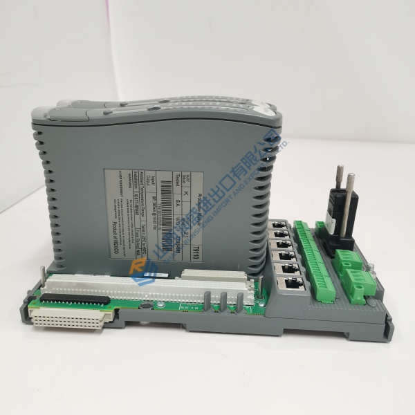
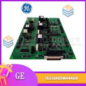
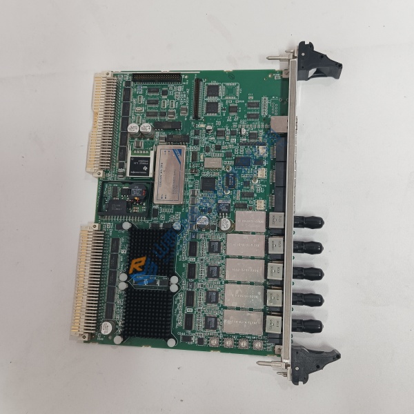
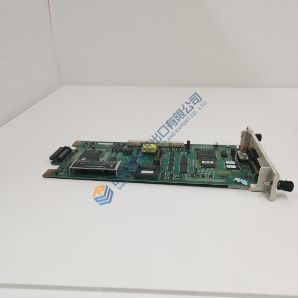
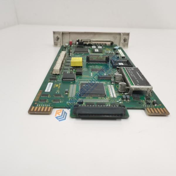
Product Introduction Integrating the GE 314A5030P01 interface board into a Speedtronic turbine control panel restores fast signal routing for critical turbine governing systems. Engineered specifically for demanding power generation operations, this card conditions control signals across internal backplane buses to prevent unexpected trip conditions in utility-scale installations.
Maintenance leads consistently source this OEM circuit card to replace degraded components during scheduled plant turnarounds. It delivers stable processing under tight execution cycles, operating dependably in control room ambient conditions between 0 °C and 60 °C.
Installation & Configuration Guide Phase 1 — Pre-Installation (est. 10 min) De-energize the turbine control cabinet completely. Wait 5 minutes for bus capacitors to bleed down before opening rack enclosures. Gather a Fluke 115 digital multimeter, anti-static wrist strap, and flathead/Phillips screwdrivers. Export the active panel configuration file, then take detailed photos of all terminal wire routing, cable connections, and hardware jumper settings.
Phase 2 — Removal (est. 5 min) Label all connected ribbon cables or terminal leads with printed wire tags before unplugging. Loosen the top and bottom retaining screws on the card faceplate. Pull the module straight outward along the card cage guide rails to prevent bending rear connector pins. Inspect the backplane slot for debris or damaged socket contacts.
Phase 3 — Installation (est. 10 min) Attach your ESD wrist strap to cabinet frame ground before opening the anti-static packaging. Verify the part number stamped on the board reads GE 314A5030P01. Match all DIP switch and jumper positions on the new board to your reference photos. Align the card with the guide rails, slide it inward until the rear pins seat firmly into the backplane socket, and tighten the retaining screws to 0.5 N·m.
Phase 4 — Power-On & Testing (est. 15 min) Check 24 V DC backplane supply voltage to verify power is stable within ±10%. Power up the control rack. Observe front status LEDs: RUN should glow solid green without diagnostic red warning lights. Connect your laptop using system diagnostic software, download configuration files, perform live signal loop checks, and verify operational stability for 30 minutes before closing the maintenance ticket.