Description
Product Introduction
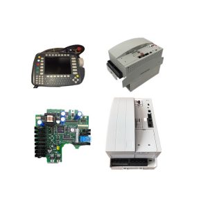
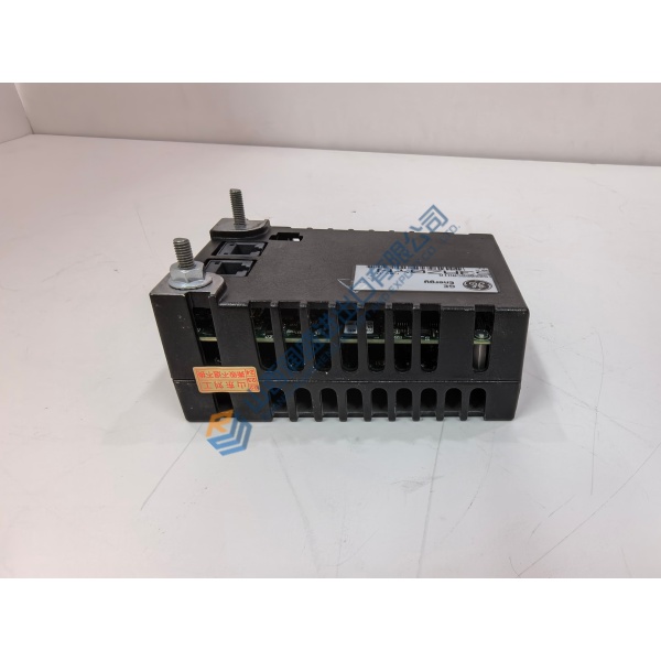
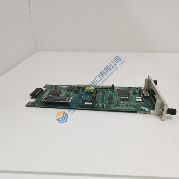
The Foxboro H90JE9A001J0 is a rack-mounted servo controller for legacy steam and gas turbine electro-hydraulic (EH) governing systems. It takes a ±10 V command from the DCS or speed regulator and drives a servo valve to position fuel valves or steam admission valves with LVDT feedback closure .
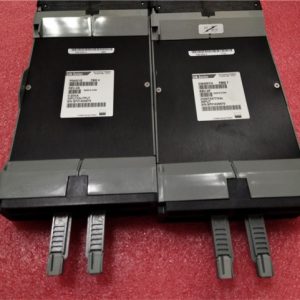
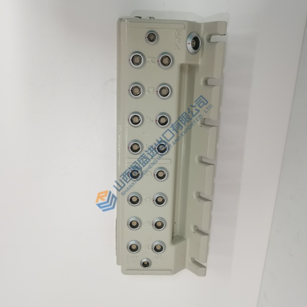
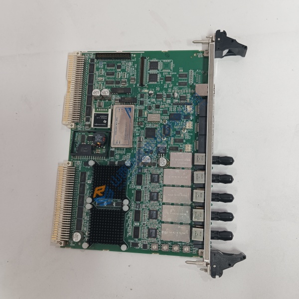
The sourcing picture is straightforward but not comfortable. Foxboro discontinued this model. Every unit in circulation is surplus, pull-out, or old stock from decommissioned turbine cabinets . That makes condition verification the whole game—a servo controller that sat in a humid warehouse can have drifted analog circuits or corroded edge connectors. Demand photos of the actual board, not a stock image. Ask for the serial number and any test data the seller holds.
Installation & Configuration Guide
Phase 1 — Pre-Installation (est. 15 min). De-energize the turbine control cabinet. Wait five minutes for supply discharge. Photograph the existing module’s slot position, rear connector pinout, and any DIP switches or potentiometers on the faceplate. Export the DEH configuration if the service tool is available. You need an ESD strap, a calibrated multimeter, and the cabinet wiring diagram showing the LVDT and servo valve terminations.
Phase 2 — Removal (est. 8 min). Label every cable at the module face—LVDT excitation, LVDT signal, servo valve drive, and command input. Release the rack retaining screws. Pull the module straight out. Inspect the backplane connector for bent pins or carbon tracking. ❗ Do not force the module. Edge connectors on legacy Foxboro racks are fragile after decades of thermal cycling.
Phase 3 — Installation (est. 10 min). ESD strap on. Verify the replacement label reads H90JE9A001J0—not a sibling model like H90JE9A002J0 or H90JB9A001J0, which share the H90 series but may carry different input/output scaling . Seat the module firmly. Reconnect cables in reverse order of removal. Verify supply voltage at the rack terminals: ±15 V DC and 24 V DC rails should be within tolerance before powering the module.
Phase 4 — Power-On & Testing (est. 20 min). Apply power. Observe the fault LED—steady off is the expected state with no command and no feedback error. Inject a known ±10 V command from a calibrator with the turbine offline. Monitor the servo valve drive current output. Verify the LVDT feedback path reads correctly by simulating the position signal or manually stroking the valve if the hydraulic system is pressurized and safe to do so. Confirm the module tracks command to feedback without oscillation. Log the module serial number and test results.