Description
Product Introduction
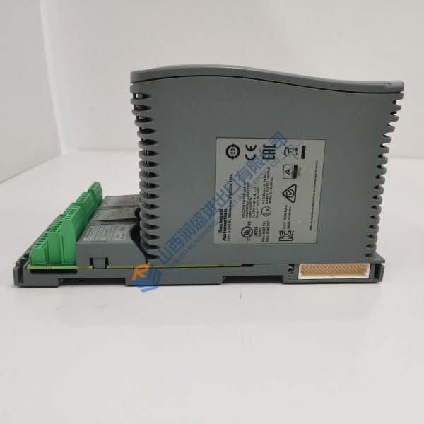
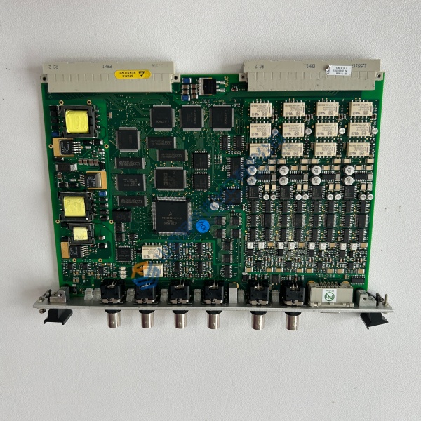
The GE F650-B-A-B-F-1-G-0-HI is a draw-out feeder protection and bay controller from the Multilin F650 line. It handles overcurrent, voltage, frequency, and breaker failure functions for distribution feeders up to 38 kV, with a graphical LCD and programmable logic for bay interlocking.
Decoding the suffix tells you exactly what lands in the box. The first B is the basic function package. A sets the rear communication board. B is the rear Ethernet board—10/100 Base TX. F-1 gives you 16 digital inputs and 8 outputs in slot F. G-0 leaves slot G empty. HI is the wide-range 110–250 V DC auxiliary supply. One thing to flag: the basic display configuration and the exact protection function set depend on the firmware loaded at the factory. Confirm the firmware revision with the seller before you commit—GE shipped F650 units across multiple major firmware generations, and the feature set moved between releases .
Installation & Configuration Guide
Phase 1 — Pre-Installation (est. 15 min). De-energize the panel. Confirm the control power supply is isolated. Export the existing relay configuration using EnerVista 650 Setup software. Photograph the rear terminal blocks, CT/VT wiring landing points, and the existing relay’s nameplate. You need a laptop with EnerVista installed, a USB or Ethernet cable, and an ESD strap.
Phase 2 — Removal (est. 10 min). Label every wire before loosening terminals—CT circuits are the critical ones. Short the CT secondaries at the test block before disconnecting. Release the draw-out latches. Pull the relay straight out of the case. Inspect the case’s rear connector pins for bent contacts or discoloration. ❗ Never open-circuit a CT secondary. The voltage spike can destroy insulation and injure personnel.
Phase 3 — Installation (est. 10 min). ESD strap on. Verify the replacement’s model suffix matches exactly—especially the HI supply code and the F-1 I/O board. Slide the relay into the case until the latches engage. Reconnect CT circuits first, then VT, then control power. Torque terminals per the F650 instruction manual. Run the pre-power checklist: no CT secondaries open, no stray strands bridging terminals, correct polarity on all current inputs.
Phase 4 — Power-On & Testing (est. 25 min). Apply auxiliary voltage. Verify the front display initializes. Connect EnerVista via the front USB or rear Ethernet port. Read the firmware version and hardware revision—record both. Download your configuration file. If the new relay’s firmware differs from the old unit, confirm the configuration file is compatible before proceeding. Perform a pickup test on one overcurrent element using a secondary injection set. Verify the trip output operates the correct breaker trip coil. Check one digital input status change in EnerVista. Log the relay serial number, firmware version, and test results in the maintenance record.
Troubleshooting quick-reference:
- Relay won’t power up → Check HI supply voltage at terminals; verify range 88–300 V DC.
- EnerVista cannot connect → Confirm IP address and subnet; check rear Ethernet port LED activity.
- Configuration download fails → Firmware mismatch between saved file and relay. Check release notes for compatibility .