Description
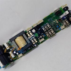
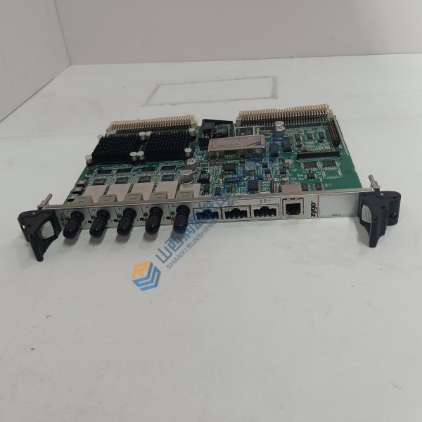
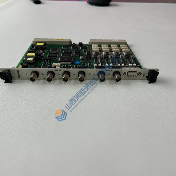
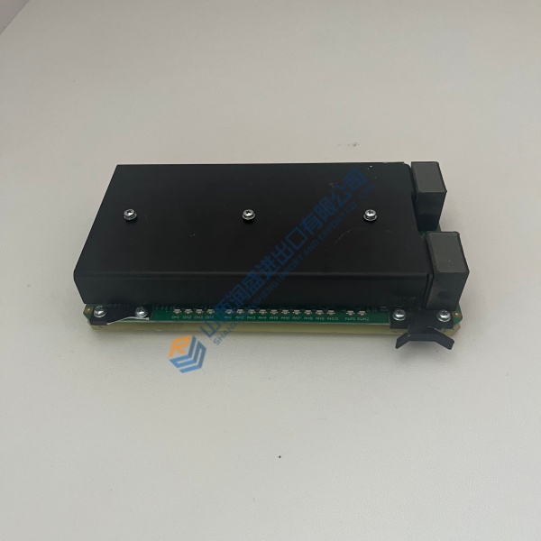
Product Introduction Integrating the Woodward 8273-1011 digital governor into a generator control panel provides high-speed frequency regulation and automatic load balancing for critical power generation. Built with a rugged, microprocessor-based architecture, this unit replaces legacy analog 2301A controls while maintaining compatibility with standard engine magnetic pickups and actuators.
Procurement managers choose this 2301E model to modernise engine management during overhaul turnarounds. It delivers fast loop execution under 10 ms, operating reliably in field cabinet conditions from -40 °C to +70 °C.
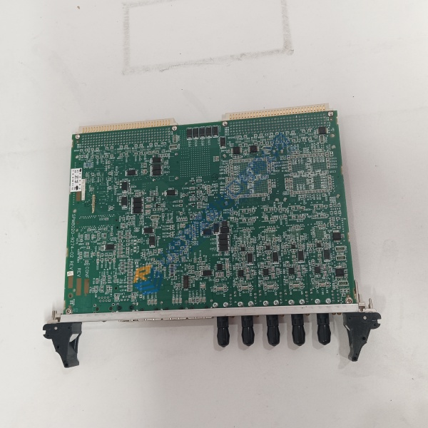
Installation & Configuration Guide Phase 1 — Pre-Installation (est. 10 min) De-energize the engine control panel completely. Wait 5 minutes for all power supply caps to discharge before opening cabinet doors. Gather a Fluke 115 digital multimeter, wire strippers, small flathead screwdrivers, and an anti-static wrist strap. Export your project configuration files using Woodward Watch Window software, then photograph existing terminal wiring blocks, shielding points, and wire tags.
Phase 2 — Removal (est. 5 min) Label every terminal screw connection using printed wire wraps before removing conductors. Loosen the terminal block screws and carefully pull off wire harness ends. Remove the four corner mounting bolts holding the existing governor control to the backpanel. Inspect the mounting area for metal shavings, grease, or chassis corrosion.
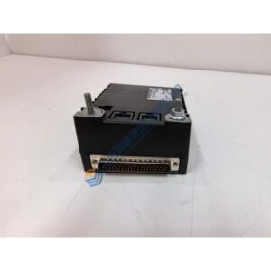
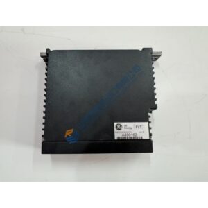
Phase 3 — Installation (est. 10 min) Put on your ESD wrist strap before unboxing the replacement governor. Verify the unit nameplate reads Woodward 8273-1011. Mount the unit securely onto the panel backplate using M5 bolts tightened to 2.5 N·m. Re-attach wiring according to your reference photographs and schematic, tightening terminal screws to ~0.5 N·m. Verify actuator and speed pickup shields connect at the controller ground terminal only.
Phase 4 — Power-On & Testing (est. 15 min) Measure 24 V DC power at the supply terminals to confirm voltage reads within 18–32 V DC limits. Apply power to the unit. Observe front panel LEDs: power indicator should illuminate steady green with no fault lights active. Connect your laptop via the RS-232 serial port, upload the 2301E configuration file, verify speed setpoints, and start the engine under manual control. Run a 30-minute load testing sequence before signing off the maintenance log.