Description
Product Introduction
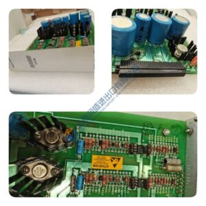
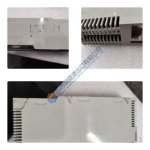
Need to capture E-stop and permissive signals with SIL 3 integrity? The ICS TRIPLEX T8403 is the Trusted TMR 40-channel 24 VDC digital input module that applies 2oo3 voting to every field point.
This unit delivers 1 ms SOE timestamping on each channel, with 2500 V impulse opto/galvanic isolation between field and backplane. In field deployments of ESD and F&G systems, we’ve seen this module handle 40 safety inputs without the nuisance trips you get on single-channel DI cards. Triple sigma-delta ADCs per channel mean a single component failure can’t force a wrong vote—the other two paths hold the correct state.
Installation & Configuration Guide
Phase 1—Pre-Installation (est. 10 min)
De-energize the T8100 chassis. Wait 5 minutes for capacitor discharge. Grab a 24 VDC multimeter, ESD wrist strap, and a camera. Export the current Trusted configuration (via TriStation). Photograph the existing T8403, field wiring terminal block, and backplane connector—photo, photo, photo.
Phase 2—Removal (est. 5 min)
Label every field input wire before disconnecting. Release the locking latches on the T8100 chassis. Slide the T8403 out carefully, keeping the backplane connector intact. Inspect the backplane connector pins for bent or corroded contacts.
Phase 3—Installation (est. 10 min)
Strap on your ESD gear. Verify the part number matches T8403. Slide the module into the T8100 slot, seat until the locking latches click. Reconnect field input wires (observe terminal numbering: 1–40). Run a pre-power checklist: backplane supply 20–32 VDC, ground continuity, no loose strands.
Phase 4—Power-On & Testing (est. 15 min)
Apply 24 VDC ±10% to the T8100 backplane. Watch the LEDs: Active = green steady, Standby = off (green = standby), Educated = green flash, Fault = off (red = fault). Connect TriStation software via RS422. Verify the 40-channel configuration downloads without errors. Run a functional test: simulate a 24 VDC input on channel 1, verify LED lights and SOE timestamp; simulate open circuit (disconnect wire), verify line monitoring alarm; simulate short circuit (short terminal to 0 V), verify fault detection. Confirm stable operation for at least 30 minutes. Log the swap in your maintenance record.