Description
Product Introduction
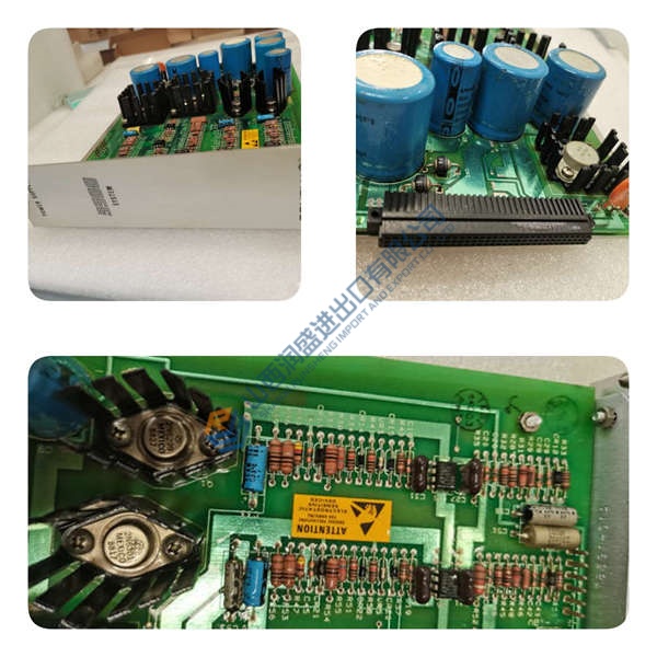
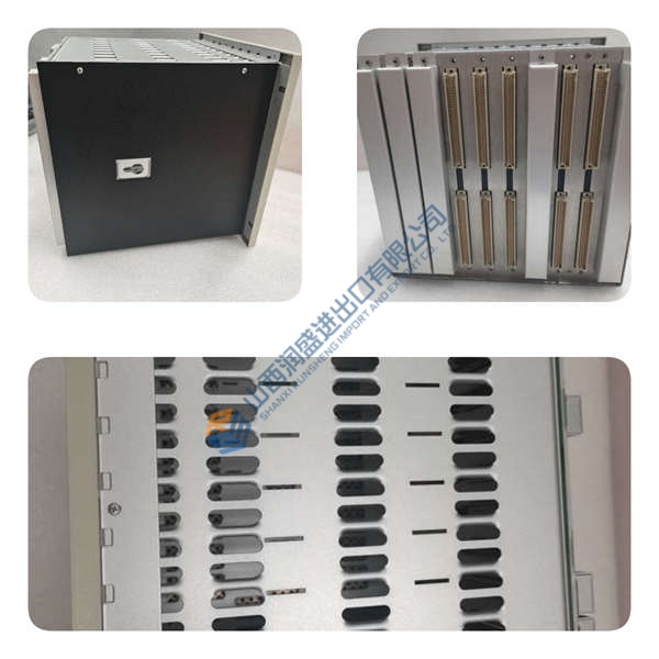
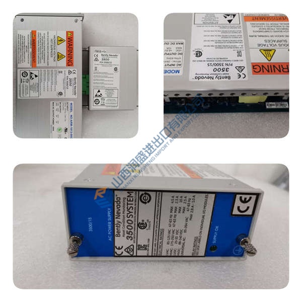
The ICS Triplex T8431 serves as a high-density analogue input interface within Trusted fault-tolerant control architectures, continuously monitoring critical field sensors across emergency shutdown and fire-and-gas loops. It accepts 40 current-sinking input channels and routes each signal through triplicated processing paths to maintain continuous operation during single-component faults.
Engineers specify the ICS Triplex T8431 when safety loops demand fast signal capture without sacrificing redundancy. Featuring a 0.5 ms sample update time and onboard Sequence of Events timestamping at 1 ms resolution, this card captures transient process spikes before downstream trips occur.
Key Selling Points & Differentiators
- High-speed 0.5 ms update rates across all 40 channels provide 1 ms Sequence of Events recording to simplify post-trip root cause analysis.
- Every field spare undergoes a 5-point quality check including 500 V megger insulation tests and a 24-hour live burn-in with complete test report generation.
- Unlike standard non-redundant 4–20 mA cards that fail unannounced, this module executes continuous 2-minute background self-tests and active line monitoring to detect open or shorted field cables instantly.
- Not recommended for applications requiring onboard intrinsic safety barriers without external Zener or galvanic isolation units installed on the field terminal block.
- Fully compliant with IEC 61508 SIL 3 standards for safety-instrumented functions.
Standard Quality Control Procedure
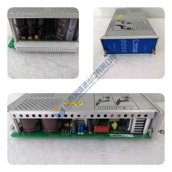
To ensure stock spare parts execute without failure upon field installation, each unit passes a documented 5-step quality verification:
- Incoming Inspection: Verification of shipping documents, visual check for pin oxidation or board aging, and serial number cross-referencing against manufacturer databases to confirm authenticity.
- Live Functional Test: Insertion into a dedicated test chassis. The module undergoes power-on self-check LED verification, communications handshake over the backplane, full-range 0–22 mA current injection across all 40 channels, and a 24-hour continuous burn-in run with temperature recording. Full test reports and video recordings are provided upon request.
- Electrical Parameter Tests: Insulation resistance testing using a 500 V megger to confirm >10 MΩ isolation between field commons and logic ground, alongside ground continuity checks.
- Firmware / Configuration Verification: Extraction and documentation of exact firmware revisions (e.g., V3.2.1) and jumper/DIP settings prior to packing.
- Final QC + Packaging: Final sign-off, sealing inside anti-static ESD bags, multi-layer bubble wrapping, heavy-duty carton packaging, and application of a dated “QC Passed” label. Passed the above checks; verified functional at time of test.
Technical Pitfall & Replacement Guide
- Firmware Revision Mismatch: Swapping a card with mismatched firmware can cause chassis communication drops or backplane configuration errors. Always query and record the active card revision via system diagnostics before pulling the old unit. Request a matching firmware range from your supplier before shipment.
- DIP Switch / Jumper Misconfiguration: ❗ Improper address or termination settings will cause channel faults or prevent system synchronization. Take high-resolution photos of the original card’s switches before removal and match all physical positions on the replacement unit.
- Terminal Block / Cable Incompatibility: Wiring pinouts and connector keying vary between system revisions. Always consult the official wiring diagram rather than relying on memory during emergency changeouts.
- Power Budget Differences: The module draws 15 to 18 W during normal operation. Verify that the local rack power supply retains at least a 20% power headroom margin (e.g., keeping total rack load under 80 W on a 100 W supply) to avoid voltage dips during full channel energization.
- ESD Handling: Static discharge can damage sensitive input multiplexers. Always wear a grounded wrist strap attached to the chassis frame and work on an ESD mat. A site technician once destroyed a fresh input board during a winter outage simply by carrying it unshielded across a carpeted control room.