Description
Product Introduction
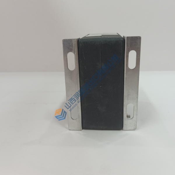
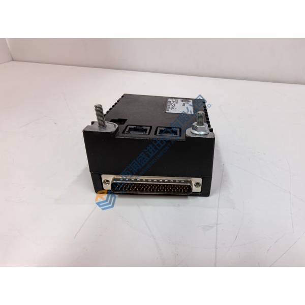
A communication failure between your control system and field metering lines can freeze telemetry data and disrupt automated processes. The PROSOFT ILX56-MM delivers continuous multi-drop serial bridging and deterministic Modbus message handling across demanding industrial plants. Designed to fit Rockwell Automation 1756 ControlLogix chassis, it mounts directly into open rack slots without needing external power supplies or custom mounting plates.
In field deployments across oil and gas, water/wastewater, and power distribution systems, this unit supports simultaneous Master and Slave protocols across two independent serial channels. The PROSOFT ILX56-MM integrates into Studio 5000 / RSLogix 5000 software using Add-On Profiles (AOP) to keep field communications running smoothly. Listed prices serve as a baseline market reference; actual costs depend on global surplus availability and current lead times. Contact our procurement team directly to request an exact quote.
Installation & Configuration Guide
Phase 1 — Pre-Installation (est. 10 min)
De-energize main 1756 chassis power supplies. Wait 5 minutes for power supply decoupling capacitors to discharge fully. Assemble a small flathead screwdriver, ESD grounding wrist strap, shield termination wire, and a digital multimeter. Export your active Studio 5000 project and save an offline configuration file. Take clear photos of all serial terminal block pinouts, shield connections, and slot positioning on the active PROSOFT ILX56-MM module.
Phase 2 — Removal (est. 5 min)
Label every serial cable and shield drain wire with port tags before disconnecting them. Unplug the removable terminal block (RTB) by releasing its top and bottom locking tabs. Press the module top and bottom chassis locking latches inward simultaneously. Slide the module straight out of the 1756 backplane slot along its card guides. Inspect the chassis backplane connector for dust or bent contacts.
Phase 3 — Installation (est. 10 min)
Put on your ESD wrist strap and bond its grounding lead to the cabinet enclosure. Remove the replacement PROSOFT ILX56-MM from its anti-static shielding bag. Verify the full part number on the side label matches your bill of materials. Align the module circuit board with the chassis guide rails and push firmly until both top and bottom latches click into place. Reattach the wired RTB connector, torquing terminal screws to ~0.3 N·m. Run a physical cabling check.
Phase 4 — Power-On & Testing (est. 15 min)
Measure incoming voltage at the chassis power supply — verify 24 V DC nominal before turning on the breaker. Apply power. Observe the front panel LED boot sequence: OK LED turns steady green, P1 and P2 LEDs flicker to indicate serial traffic, and ERR LEDs remain off. Open Studio 5000, verify module health status in the I/O tree, and import the module Add-On Instruction (AOI) data tags. Monitor Modbus transaction counters for 30 minutes to verify error-free communications. Record the replacement in your plant maintenance logs.