Description
Product Introduction
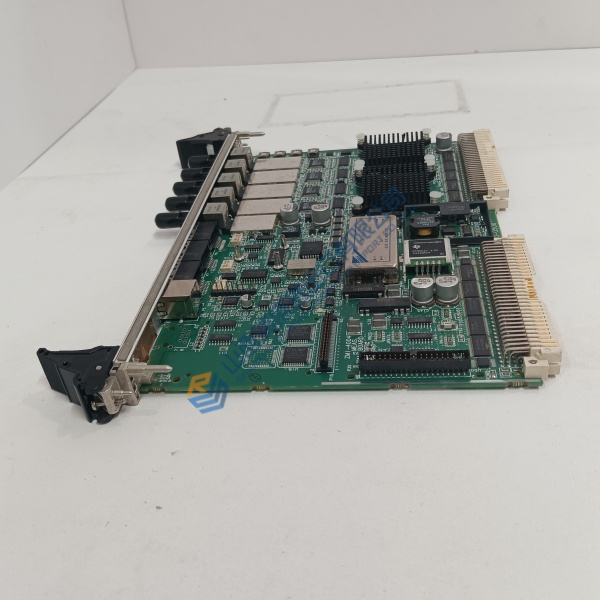
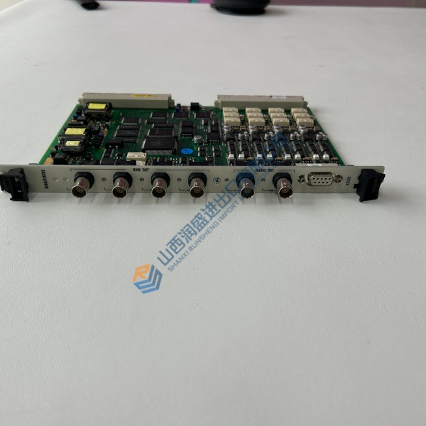
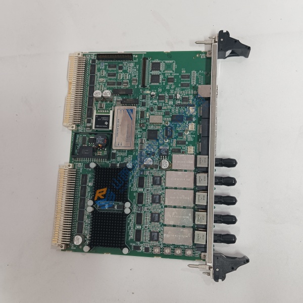
The Woodward 8440-2085 is an easYgen-3500XT-P1 paralleling genset controller. It handles synchronization, load sharing, breaker control, and engine protection for plants running multiple generators against a utility or in island mode.
The P1 package is the key detail. It includes the I/O set and CANopen connectivity for up to 16 LS-5 circuit breaker controls, enabling load sharing across up to 32 generators on 32 bus segments . Direct connection to 690 V AC eliminates step-down PTs in most medium-voltage applications. The controller operates at 4,000 m altitude without derating —a spec that matters if your site sits in mountainous terrain. Supply range of 8–36 V DC covers both 12 V and 24 V battery systems with margin .
Installation & Configuration Guide
Phase 1 — Pre-Installation (est. 20 min). De-energize the control panel. Export the existing controller’s configuration file using Woodward ToolKit. Photograph the rear terminal wiring—PT/CT circuits, breaker control outputs, and CAN bus terminations. You need an ESD strap, a laptop with ToolKit installed, and the plant’s synchronization and protection settings on hand.
Phase 2 — Removal (est. 10 min). Label every wire at the rear terminals. Open the PT circuits only after confirming the panel is de-energized. Disconnect CAN bus cables and note the 120 Ω termination resistor positions. Release the panel retaining clips. Pull the controller straight out.
Phase 3 — Installation (est. 12 min). ESD strap on. Verify the replacement label reads 8440-2085 and note the revision letter—K and L both appear in surplus listings . Confirm supply voltage at the panel terminals: 8–36 V DC. Seat the controller into the cutout. Reconnect wiring in reverse order of removal. Verify CAN bus termination resistors remain at both physical ends of the bus.
Phase 4 — Power-On & Testing (est. 25 min). Apply 24 V DC. Observe the display initialization. Connect via Ethernet or USB with ToolKit. Read the controller’s firmware revision and record it. Download your configuration file. If the replacement’s firmware differs from the old unit, check ToolKit for compatibility before proceeding. Verify PT and CT readings against a known reference. Test one synchronization sequence with the generator offline if possible. Confirm breaker control outputs operate the correct coils. Log the serial number, firmware version, and test results.
Troubleshooting quick-reference:
- Controller does not power up → Check supply voltage at terminals; verify 8–36 V DC range.
- CAN bus communication failure → Confirm 120 Ω termination at both bus ends and correct cable pinout.
- ToolKit cannot connect → Verify IP address settings and Ethernet cable; check USB driver installation.