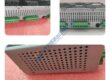
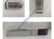
Product Core Brief
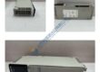
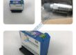
- Model: REM615 HBMBCAAJNAA1BNN1XG
- Brand: ABB
- Series: Relion 615 Series
- Core Function: Provides dedicated motor protection, control, measurement, and supervision in medium-voltage industrial power systems.
- Type: Feeder / Motor Protection Relay
- Key Specs: 3-phase current inputs, residual current input, 3-phase voltage inputs, residual voltage input, Modbus/IEC 61850 protocols, 24–240 V DC / 100–240 V AC auxiliary power supply.
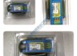
- Condition: New Original (New Surplus)
- Availability: Direct shipment available; standard lead time is 3–5 business days from order confirmation.
- Warranty: 12-month operational warranty backed by supplier verification.
Pricing Note: The listed price serves as a reference point only. Actual spot market pricing fluctuates based on component availability and global logistics supply lines. Contact procurement to request a formal quote.
Product Introduction
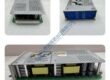
In field deployments of AC800M systems and medium-voltage switchgear networks, motor failures disrupt entire production lines instantly. The ABB REM615 HBMBCAAJNAA1BNN1XG motor protection relay operates as a dedicated intelligence hub, monitoring thermal overload, overcurrent, and phase unbalance. This module integrates seamlessly into standard distribution panels, shielding critical pumps, fans, and compressors from electrical faults.
Engineering teams prioritize this unit because it natively executes the complex IEC 61850 automation protocol. This specific relay drives down network latency, executing fault detection sequences in under 15 ms. Well, technically it supports multiple bus topologies, but maximum speed requires dedicated Ethernet fiber links. Operating reliably from −25 to +55 °C, the hardware mitigates risk across demanding industrial footprints.

Installation & Configuration Guide
Phase 1 — Pre-Installation (est. 10 min)
Isolate all upstream breakers feeding the switchgear panel. De-energize the entire bay and wait a minimum of 5 minutes for internal filter capacitors to fully discharge. Grab your insulated screwdriver set, a Fluke 115 multimeter, and your anti-static wrist strap. Export the current parameter file from the PCM600 software tool if you are replacing an active unit. Photograph the existing wire markers, rear terminal layout, and physical grounding wire routing.
Phase 2 — Removal (est. 5 min)
Label every individual wiring terminal block clearly before backing out any screws. Pull the compression terminal blocks straight back from the rear panel. Release the upper and lower flush-mount fixing clamps using a standard crosshead screwdriver. Pull the module perpendicular to the cutout, keeping it completely level to avoid scratching the panel face. Inspect the backplane connector pins for any signs of arcing or localized discoloration.
Phase 3 — Installation (est. 10 min)
Strap on your ESD grounding wristband before opening the factory sealed packaging. Verify the exact label on the side of this module matches the procurement order sheet. Slide the unit smoothly into the panel cutout until the integrated rubber gasket seats firmly against the steel sheet. Tighten the mounting bracket screws to exactly 0.5 N·m of torque to guarantee an IP54 seal. Reconnect the terminal blocks, ensuring the grounding strap routes directly to the main copper earth busbar.