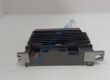
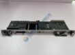
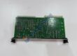
Product Core Brief
- Model: FSM 006A64 (se@vis FSM)
- Brand: SAACKE
- Series: se@vis Burner Control Architecture
- Core Function: Electronic actuator / flame safety module managing damper position, fuel valve modulation, and safety bus interlocks.
- Type: Electronic Servomotor / Flame Safety Actuator Module
- Key Specs: Integrated fail-safe communication interface (Safe-Ethernet), precision feedback, IP65 housing
- Condition: New Original (New Surplus) / Tested Surplus
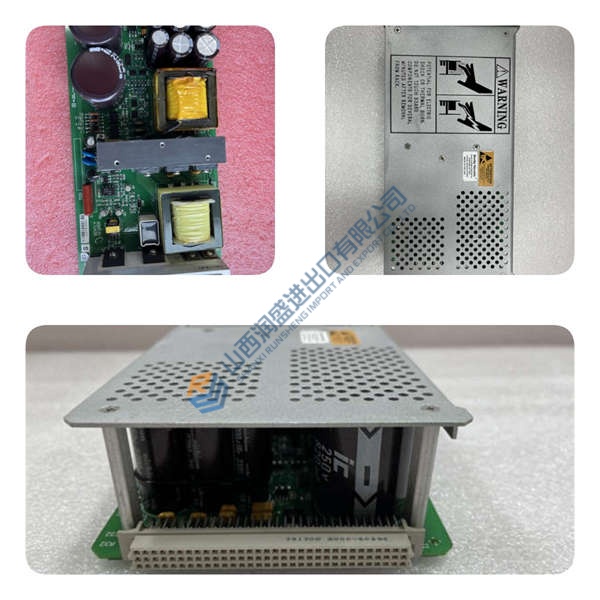
Product Introduction
In marine boilers and heavy industrial burner installations running SAACKE combustion control systems, precise fuel-to-air ratio control is essential for fuel efficiency and emissions compliance. The SAACKE FSM 006A64 (se@vis FSM) functions as an intelligent, fail-safe electronic actuator that modulates fuel valves and air dampers while maintaining active communication with the master burner management system (BMS).
Engineers specify the FSM 006A64 module for SAACKE marine and land-based boilers because it integrates safety-critical Ethernet communication directly into the actuator housing. Replacing a faulted actuator with a factory-tested unit restores automatic firing sequence timing, eliminates combustion hysteresis, and prevents emergency burner trip lockouts.
Key Selling Points & Differentiators
- Dual Safe-Ethernet ports enable bus topology networking between multiple burner actuators and the main se@vis controller without external position positioners.
- High-torque brushless DC motor coupled with a precision gearhead provides zero-backlash positioning on air butterfly dampers and rotary oil valves.
- Integrated fail-safe logic returns the actuator to a predefined safety shutdown position upon loss of power or communication.
- Every surplus SAACKE FSM unit undergoes a 5-point quality check including high-potential insulation checks and a continuous 24-hour live communication burn-in run.
- Rugged IP65 industrial enclosure resists oil mist, high vibration, and marine engine room ambient conditions.
Standard Quality Control Procedure
To guarantee immediate field operational readiness upon arrival, every unit completes a structured 5-step engineering verification protocol:
- Incoming Inspection: Visual check of aluminum casting integrity, shaft keyway condition, connector pin inspection, and serial/part number cross-referencing against OEM records.
- Live Functional Test: Mounting on a SAACKE se@vis test bench. The actuator undergoes power-up diagnostic sweeps, Safe-Ethernet link negotiation, full 0–90° travel positioning sweeps, speed curve validation, and a continuous 24-hour thermal burn-in run. Test reports are available upon request.
- Electrical Parameter Tests: Megger insulation testing between 24 V power terminals and outer chassis frame (>10 MΩ target), alongside motor current draw verification across full load range.
- Firmware / Address Configuration: Verification of internal encoder zero points, firmware builds, and bus node identification parameters.
- Final QC + Packaging: Final engineering sign-off, sealing electrical connections with protective caps, multi-layer ESD and bubble wrapping, heavy-duty carton packaging, and attachment of a dated “QC Passed” label. Passed the above checks; verified functional at time of test.
Technical Pitfall & Replacement Guide
- Unaligned Zero Position Calibration: ❗ Installing a replacement actuator without matching its mechanical zero position to the physical damper or valve linkage will cause incorrect fuel/air mixing ratios and flame instability. Always verify mechanical linkage alignment and execute a software calibration sweep via the se@vis terminal upon installation.
- Bus Node Address Conflicts: Dual Safe-Ethernet configurations require unique IP/node assignments within the se@vis network. Assigning duplicate addresses will drop communication across the entire safety loop.
- Cable Shielding & Grounding: Engine room electromagnetic interference (EMI) can disrupt high-speed Ethernet communication. Ensure double-shielded industrial Ethernet cables are used and properly grounded at the cable gland entry points.
- Power Supply Drops: Inductive voltage drops on 24 V dc power supply lines during heavy actuator movement can cause module micro-resets. Maintain adequate power supply capacity with a 20% power headroom margin.
- ESD Handling: Technicians must wear grounded ESD wrist straps when handling or connecting open wiring terminals to protect internal microprocessor circuits from static discharge.
Remember these and you’ll avoid most rework.