Product Core Brief
- Model: 0010-37148
- Brand: AMAT (Applied Materials)
- Series: Semiconductor Processing Equipment Electronics / PCBA Subsystem
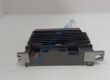
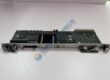
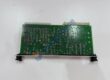
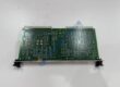
- Core Function: Serves as a dedicated electronic control board assembly for real-time signal processing and module communication within Applied Materials tool platforms.
- Type: Printed Circuit Board Assembly (PCBA) / Electronic Control Module
- Key Specs: Multi-layer industrial PCB, precision component array, gold-plated edge/bus connectors, multi-rail DC voltage inputs
- Condition: Condition: New Original (New Surplus) — not refurbished. Verified secondary market options tested prior to shipment.
Product Introduction
A control board failure inside an Applied Materials semiconductor processing tool can halt wafer transfers or interrupt critical plasma chamber routines, leading to costly yield loss. The AMAT 0010-37148 PCB assembly delivers precise signal distribution, low-noise data processing, and reliable communication across wafer handling and process control subsystems. Designed to OEM specifications, it drops directly into standard card cages and electronics racks without physical or electrical modification.
Deployed worldwide in 200mm and 300mm fabrication facilities, this board assembly maintains signal integrity in high-frequency, high-temperature tool environments. The AMAT 0010-37148 communicates seamlessly with central tool controllers to keep production lines running at peak throughput. Listed prices serve as a baseline market reference; actual costs depend on global surplus availability and current lead times. Contact our procurement team directly to request an exact quote.
Installation & Configuration Guide
Phase 1 — Pre-Installation (est. 10 min)
Follow facility lock-out/tag-out (LOTO) procedures to safely power down the tool electronics rack before opening bay doors. Assemble a precision Phillips screwdriver, torque driver, ESD grounding wrist strap, and a digital multimeter. Backup current tool calibration data and module parameter files via the main operator console. Take clear photos of all ribbon cables, jumper positions, and DIP switch settings on the active AMAT 0010-37148 unit.
Phase 2 — Removal (est. 5 min)
Attach your ESD wrist strap to the cabinet grounding bus. Carefully label and disconnect all ribbon cables or coaxial lines attached to the front panel. Loosen the captive retention thumbscrews at the top and bottom of the card faceplate. Unlatch the card ejector handles simultaneously to disengage the board from the backplane, then pull the module straight out along the guide rails. Inspect the rack backplane connectors for dust or pin damage.
Phase 3 — Installation (est. 10 min)
Remove the replacement AMAT 0010-37148 from its anti-static shielding bag and verify the part number label. Match all DIP switches and jumper blocks to the original board settings recorded in Phase 1. Align the edges of the PCB with the card cage guide tracks, sliding it smoothly inward until the ejector levers catch the chassis lip. Press the levers flat to firmly seat the edge connector into the backplane, then tighten the panel screws to ~0.5 N·m. Reconnect all front-panel interface cables according to your labels.
Phase 4 — Power-On & Testing (est. 15 min)
Verify clean DC voltage levels at the rack power bus before energizing the bay. Restore power to the tool cabinet. Observe the onboard LED status indicators: POWER LEDs illuminate solid green, FAULT indicators clear after self-check completion, and BUS COMM LEDs display active polling. Boot the tool software, run the diagnostic self-test suite for the targeted subsystem, and verify error-free communication with the main controller. Log the replacement details in your fab maintenance management system.