Product Core Brief
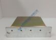
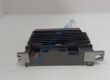
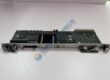
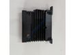
- Model: H1111.0103
- RR Part Number: 75669
- Brand: Rolls-Royce Marine (Kongsberg Maritime)
- Series: Marine Controller / CANman Control System Series
- Core Function: Central processor executing real-time propulsion management, thruster control, and vessel automation loops.
- Type: Marine Controller Unit (6029 / 300 MHz)
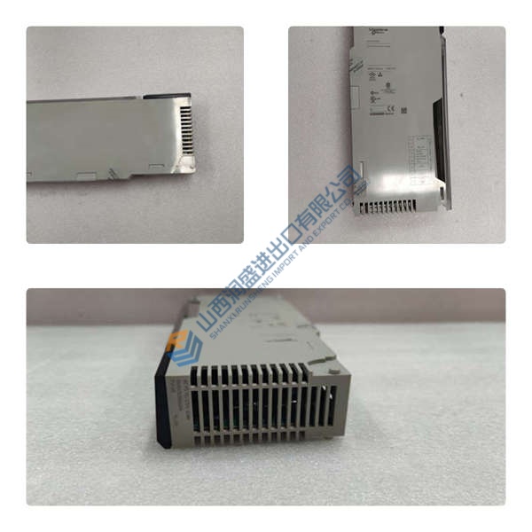
- Key Specs: Dual LAN ports, multiple CAN bus interfaces, 24 V dc power input, rugged marine-grade stainless housing
- Condition: New Original (New Surplus) / Tested Surplus
Product Introduction
Maintaining real-time communication between bridge command levers and engine room actuators requires dependable marine-grade processing hardware. The Rolls-Royce H1111.0103 (RR Part 75669) functions as an embedded central controller within Rolls-Royce Marine and CANman propulsion management networks.
Operating at 300 MHz, this marine controller manages high-speed CAN bus routing, analog/digital I/O polling, and network communication across thrusters, main propulsion engines, and dynamic positioning interfaces. Installing a factory-tested unit restores full bridge-to-engine communication and resolves processor fault alarms during vessel overhauls or emergency offshore repairs.
Key Selling Points & Differentiators
- Built specifically for harsh marine engine room and bridge console environments with high EMC shielding and vibration resistance.
- Integrates multiple CAN bus interfaces alongside dual Ethernet LAN ports to support redundant marine network topologies.
- Pre-tested onboard BIOS and PIC-code firmware execution ensuring plug-and-play field restoration when replacing faulted processing hardware.
- Every surplus Rolls-Royce H1111.0103 module undergoes a 5-point quality check including 500 V megger isolation tests and a continuous 24-hour live bench test.
- Fully compatible with legacy Rolls-Royce Marine automation architectures now supported by Kongsberg Maritime systems.
Standard Quality Control Procedure
To guarantee immediate operational readiness upon delivery to drydocks or offshore vessels, every unit completes a structured 5-step engineering verification protocol:
- Incoming Inspection: Visual check of stainless steel housing, connector pin integrity across all D-sub and RJ45 ports, terminal block threads, and serial label cross-referencing.
- Live Functional Test: Insertion into a calibrated marine controller test bench. The module undergoes power-up diagnostic routines, BIOS verification (e.g., KS029003.007 release), PIC-code revision validation, active CAN bus pinging across all channels, Ethernet link checks, and a continuous 24-hour thermal burn-in run. Test reports are available upon request.
- Electrical Parameter Tests: Megger insulation tests between 24 V dc power input pins and the outer enclosure ground (>10 MΩ target), alongside input voltage tolerance checks across 18–32 V dc.
- Firmware & SW Code Verification: Extraction and verification of onboard BIOS and PIC revisions to ensure system software compatibility before dispatch.
- Final QC + Packaging: Final engineering sign-off, protective caps applied to all serial and LAN ports, multi-layer ESD and bubble wrapping, heavy-duty shipping packaging, and attachment of a dated “QC Passed” label. Passed the above checks; verified functional at time of test.
Technical Pitfall & Replacement Guide
- BIOS / PIC-Code Version Mismatch: ❗ Inserting a controller module with an unaligned BIOS or PIC-code version (e.g., PIC rev 3.2 vs 2.1) can cause network synchronization failures with adjacent bridge units or remote I/O blocks. Always check and match the BIOS/PIC label specifications on the existing module before installation.
- Dual Power Supply Headroom: Marine 24 V dc distribution networks experience heavy voltage fluctuations during generator switching or thruster startup. Ensure local power supplies maintain a 20% power headroom margin (keeping total load under 80% rated capacity) to prevent micro-controller brownouts.
- Cable Shielding & Grounding: CAN bus and serial network lines must be terminated properly with continuous cable shielding connected to the chassis ground rail. Unterminated or double-grounded shields induce ground loop noise that causes packet loss and thruster communications failure.
- IP Address & Station ID Assignment: When swapping controllers on an active vessel network, update the station address and network configuration to match the replaced unit to avoid IP conflicts on the marine LAN.
- ESD Handling: Technicians must wear grounded ESD wrist straps when attaching communication cables or handling internal connections to protect sensitive microprocessor buses from static damage.