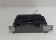
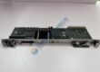
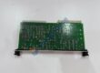
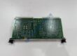
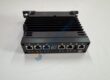
Product Core Brief
- Model: ZMI-4104C (8020-0700)
- Brand: ZYGO Corporation (AMETEK Ultra Precision Technologies)
- Series: ZMI 4000 Series Measurement Electronics
- Core Function: Multi-axis sub-nanometer optical displacement measurement and velocity tracking for precision motion stages.
- Product Type: VMEbus Laser Interferometer Measurement Board
- Key Specs: 4 Independent Optical Measurement Channels | Sub-Nanometer Resolution | VMEbus Interface Condition: New Original (New Surplus) / Fully Bench-Tested Refurbished
Product Introduction
The ZYGO ZMI-4104C is a high-performance, 4-axis laser interferometer measurement board designed for ultra-precision position feedback in semiconductor manufacturing and advanced metrology equipment. Operating inside a standard 6U VMEbus chassis, this card processes heterodyne optical interference signals generated by ZYGO laser heads and remote optical receivers to deliver real-time, sub-nanometer displacement tracking.
Engineered specifically for demanding applications like wafer stage positioning, reticle mask alignment, and coordinate measuring machines (CMM), the ZMI-4104C decodes phase information from up to four optical axes simultaneously. Its low latency and high bandwidth enable tight servo-loop integration, ensuring deterministic motion control in high-acceleration stage environments.
Quality Control & Inspection Process
Surplus metrology electronics require rigorous testing to guarantee cleanroom-grade stability and sub-nanometer accuracy. Every unit undergoes a strict 5-step quality verification process:
- Inbound Visual & Mechanical Inspection: Verify serial tags and PCB revisions against OEM manufacturing databases. Inspect the 6U front panel, fiber-optic ST/FC connectors, and gold VME backplane edge connectors for micro-cracks, contamination, or pin misalignment.
- Optical Signal & Input Channel Verification: Connect the board to a calibrated ZYGO heterodyne laser system and optical receivers using multi-mode fiber patch cables. Verify signal lock, Doppler frequency shift decoding, and signal-to-noise ratio (SNR) across all 4 independent measurement channels.
- Live VMEbus & Dynamic Bench Testing: Install the module into a VME64 test rack. Execute high-speed position tracking, continuous dynamic velocity runs, and multi-axis interpolation testing over a 24-hour continuous burn-in cycle.
- Memory & Firmware Auditing: Read and archive the onboard FPGA firmware build and configuration EEPROM data. Clear historic error flags and verify system register access over the VME bus.
- Cleanroom Packaging & Shipping: Clean optical ports with lint-free instruments, install protective dust caps over fiber interfaces, seal the card in metallic ESD shielding bags, and pack within a heavy-duty container lined with high-density anti-static foam.
Technical Pitfall & Installation Guide
Avoid these common integration errors during field replacement:
- Fiber Optic Port Contamination: Microscopic dust or oil on optical fiber connectors causes severe attenuation of the heterodyne return signal, leading to optical signal loss (Doppler dropout) during high-speed stage motion. Always clean fiber ends with isopropyl alcohol and inspect with a fiber scope before mating.
- Laser Head Frequency Alignment: Ensure the reference signal frequency from the ZYGO laser head matches the configured processing clock on the ZMI-4104C. Mismatched reference frequencies cause phase-lock errors and erratic position reporting.
- VME Backplane Power Stability: Sub-nanometer measurement circuits are extremely sensitive to supply ripple. Verify that the VME power supply delivers clean +5 VDC and ±12 VDC with low noise (<50 mV peak-to-peak) under dynamic load.
- Board Jumper & Address Settings: Mismatched VME base address jumpers or interrupt vector settings cause address conflicts on the VME bus (resulting in Bus Errors / BERR). Photograph and replicate all jumper configurations from the existing card prior to insertion.