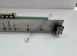
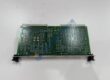
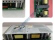
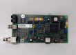
Product Core Brief
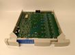
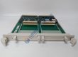
- Model: FCP280 (P0926CP)
- Brand: FOXBORO / Schneider Electric
- Series: Foxboro Evo / I/A Series DCS
- Core Function: Executes high-speed process control algorithms and coordinates fieldbus I/O modules.
- Type: Field Control Processor (DCS CPU)
- Key Specs: 2 Gbps Field Control Network interface, dual-redundant architecture, 128 MB memory
- Condition: New Original (New Surplus) — not refurbished
Product Introduction Tired of execution delays and communication bottlenecks on your distributed control system? Integrating the FOXBORO FCP280 processor unit eliminates scan latency across complex I/A Series and Foxboro Evo control nodes.
This field control processor handles multi-loop PID execution while driving high-speed data throughput across 100 Mbps Field Control Networks. Operating this processor inside petrochemical or power generation facilities cuts control scan intervals to sub-millisecond precision.
Key Technical Specifications
- Manufacturer: Foxboro (Schneider Electric)
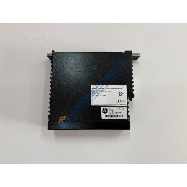
- Part Number: FCP280
- Master Part Number: P0926CP
- System Platform: Foxboro Evo / I/A Series System
- Processor Type: Field Control Processor
- Memory Capacity: 128 MB SDRAM / 32 MB Flash
- Communication Ports: 100 Mbps Field Control Network (FCN), HDLC Fieldbus
- Operating Supply: 24 V DC system backplane power
- Redundancy: Supports 1:1 fault-tolerant paired operation
- Operating Ambient: 0 °C to +60 °C
Installation & Configuration Guide
Phase 1 — Pre-Installation (est. 10 min) De-energize node power distribution modules feeding the targeted mounting base. Wait 5 full minutes for internal rack power supply capacitors to discharge safely. Gather ESD wrist straps, slot screwdrivers, and a Fluke 115 multimeter. Export database backups and block configurations from the Foxboro Control Software (FCS) engineering station. Photograph current letterbug switch settings, module positions, and network cable connections.
Phase 2 — Removal (est. 5 min) Disconnect network cables by pressing side release tabs on RJ-45 connectors. Unscrew top and bottom module retention screws securing the processor to the baseplate. Pull the old module straight forward away from the baseplate connectors without twisting, protecting rear pin arrays from mechanical strain.
Phase 3 — Installation (est. 10 min) Equip your ESD wrist strap before removing protective static shielding bags. Verify module part numbers confirm the FOXBORO FCP280 matches your site system specification. Replicate two-character Letterbug rotary switch settings from the original module onto the replacement unit. Align top and bottom module tracks with baseplate slots, pressing firmly until connectors engage completely. Tighten retention screws to ~0.5 N·m.
Phase 4 — Power-On & Testing (est. 15 min) Reapply 24 V DC system power; verify voltage levels measure within 24 V DC ±10%. Observe front panel LEDs during bootup: confirm POWER LED lights solid green while DIAG or FAIL indicators remain dark. Connect from the Foxboro engineering station, verify online status for the node, and perform initial system load checks. Monitor continuous execution for 30 minutes, checking system error logs before entering the hardware change into plant records.
Troubleshooting Quick-Reference
- FAIL LED Solid Red: Hardware self-test failure or corrupt bootloader; perform cold restart or re-flash system firmware.
- FCN Link Off: Check Ethernet patch cables, switch port status, and verify RJ-45 connector seating.
- Letterbug Mismatch: Verify rotary switch positions match exact system configuration definitions in software.