Product Core Brief
- Model: MVME7100 (variants: -0161, -0163, -0171-2GF, -0173-2GF, ET extended temp)
- Brand: Motorola (now Artesyn Embedded Technologies / Penguin Solutions)
- Series: MVME7100 VMEbus Single Board Computers
- Core Function: High-performance 6U VMEbus CPU module for industrial, defense, and aerospace embedded systems.
- Type: VMEbus Single Board Computer (SBC)
- Key Specs: 1.06/1.3 GHz MPC864xD dual PowerPC e600 cores; 1–2 GB DDR2 ECC RAM; 4× Gigabit Ethernet; 2eSST VMEbus (up to 320 MB/s); −40 °C to +71 °C extended temp option
- Condition: New Original (New Surplus) — not refurbished
⚠️ Note: Product reached EOL March 15, 2024; limited stock available. Verify exact part number and firmware before ordering.
Product Introduction
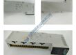
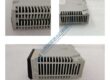
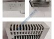
In legacy VMEbus racks running MVME2600/2700 or MVME5500/6100 boards, the Motorola MVME7100 shows up as the go-to migration path when you need more CPU horsepower without ripping out the whole chassis. It’s a 6U single-board computer built around the NXP (Freescale) MPC864xD dual-core PowerPC e600 processor—designed to slot into existing VME64x backplanes and keep your PMC/XMC expansion intact.penguinsolutions+2
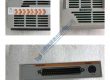
What makes this module stick is the balanced I/O subsystem: 2eSST VMEbus hits up to 320 MB/s, four Gigabit Ethernet ports land on front panel and P2 connector, and dual PMC-X sites support 33/66/100 MHz 64-bit modules. Warm-up isn’t a thing here—power-on self-test runs in seconds, and VxWorks/Linux BSPs boot in under 30 seconds on typical configs. Honestly, if your spec calls for deterministic real-time control with heavy I/O, this is the board you spec. Just watch the backplane compatibility—2eSST needs a 5-row VME64x slot, not the old 3-row VME64.
Installation & Configuration Guide
Phase 1 — Pre-Installation (est. 10 min)
- De-energize VME chassis; wait 5 min for capacitor discharge.
- Tools: ESD wrist strap, insulated screwdrivers, torque driver (0.5 N·m), multimeter (Fluke 115 or equivalent), camera/phone.
- Backup tasks: Export current VME configuration, photograph jumper settings (J30, J10, J15–J18, J25–J28), DIP switches, wiring labels, and rack layout. Record existing firmware version via MOTLoad or VxWorks
vmeConfigShow().
Phase 2 — Removal (est. 5 min)
- Label all front-panel cables and P2 rear connections before disconnecting.
- Release IEEE/Scanbe handle latches; pull module perpendicular to backplane.
- Inspect P1/P2 backplane connector pins for bent pins or corrosion—critical on older 5-row VME64x backplanes.
Phase 3 — Installation (est. 10 min)
- Ground yourself (ESD strap + mat). Verify part number matches order (MVME7100-0171 vs. -0163, etc.).
- Replicate jumper config from photos (especially J30 for Ethernet/PMC routing, J10/J15–J18 for PMC mode).
- Seat module until handle latches click; reconnect front-panel Ethernet/serial/USB.
- Run pre-power checklist: backplane voltage +5 V ±5%, VME slot compatibility (5-row for 2eSST), cooling airflow ≥200 LFM.
Phase 4 — Power-On & Testing (est. 15 min)
- Apply power; observe front-panel LEDs (CPU RUN green, BRDFAIL red).
- Connect via front serial port (115 kbps default) or Ethernet; access MOTLoad firmware monitor.
- Verify VMEbus enumeration (Tsi148 bridge detection), run POST, boot OS (VxWorks/Linux).
- Functional test: ping all 4 Ethernet ports, toggle serial loopback, test PMC slots with known-good modules, run memory test (DDR2 ECC).
- Confirm stable operation for >30 min; log swap in maintenance record with firmware version and jumper config.