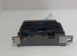
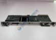
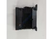
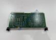
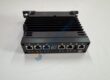
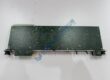
Product Core Brief
- Model: 0P0284AC (also referenced as 0P0284)
- Brand: GUTOR (now Schneider Electric / Gutor Electronic LLC)
- Series: GUTOR Industrial UPS Control Board / Power Module
- Core Function: Control board and power module for legacy GUTOR industrial uninterruptible power supply (UPS) systems.
- Type: UPS Control Board / Inverter Module
- Key Specs: 220 VDC intermediate circuit; supports 380/400/415 VAC 3-phase input/output; IP20 protection; −10 °C to +40 °C operating temp
- Condition: New Original (New Surplus) — not refurbished
⚠️ Discontinued — limited stock. This is an obsolete component for legacy GUTOR UPS installations. Verify exact part number and firmware before ordering.sxxyd+1
Product Introduction
In legacy GUTOR PxW, PXC, or PEW UPS racks still running in power plants, refineries, and data centers, the GUTOR 0P0284AC shows up as the critical control board that keeps the inverter and static switch synchronized. It’s the brain + power interface for the UPS module—managing DC-to-AC conversion, battery charging logic, and bypass transfer within the GUTOR industrial UPS architecture.sxxyd+2
What sets this board apart isn’t raw specs—it’s compatibility. The 0P0284AC ties into GUTOR’s intermediate DC circuit (110/125/220/400 VDC options) and handles 3-phase 380/400/415 VAC input/output with ±10% tolerance. Response time on transfer lands under 25 ms, voltage regulation holds at ±1% static, and the board supports Modbus TCP/RS-485 comms for SCADA integration. Honestly, if your spec calls for keeping a 10–60 kVA GUTOR rack alive without a full retrofit, this is the spare you stock. Just verify the DC bus voltage and firmware revision—more on that below.
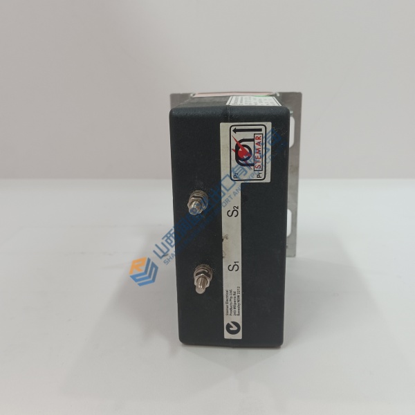
Installation & Configuration Guide
Phase 1 — Pre-Installation (est. 10 min)
- De-energize UPS system; wait 5 min for DC bus capacitor discharge.
- Tools: ESD wrist strap, insulated screwdrivers, torque driver (0.5 N·m), multimeter (Fluke 115 or equivalent), camera/phone.
- Backup tasks: Export current UPS configuration via Modbus or front-panel HMI, photograph jumper settings, DIP switches, wiring labels, and rack layout. Record existing firmware version from HMI or service tool.
Phase 2 — Removal (est. 5 min)
- Label all DC bus bars, AC input/output cables, and control wiring before disconnecting.
- Release module latches or DIN rail clips; pull module perpendicular to backplane.
- Inspect backplane connector pins for bent pins or corrosion—critical on older GUTOR racks.
Phase 3 — Installation (est. 10 min)
- Ground yourself (ESD strap + mat). Verify part number matches order (0P0284AC, not 0P0284AB or other revision).
- Replicate jumper/DIP config from photos (especially DC bus voltage selection, communication mode).
- Seat module until latch clicks; reconnect wiring to specified torque (~0.5 N·m for control terminals).
- Run pre-power checklist: DC bus voltage within tolerance (e.g., 220 VDC ±10%), AC input phase rotation correct, bypass source available.
Phase 4 — Power-On & Testing (est. 15 min)
- Apply power; observe HMI startup and LED status (RUN green, FAULT red, BYPASS amber).
- Connect via Modbus TCP/RS-485 or front-panel HMI; verify communication handshake.
- Download/verify configuration; run functional test on inverter, rectifier, static switch, and battery charger.
- Confirm stable operation for >30 min in online mode; log swap in maintenance record with firmware version and configuration backup.
Troubleshooting Quick-Reference
- No display / FAULT steady → Check DC bus voltage, reseat module, verify jumper for correct DC voltage selection.
- Inverter won’t start → Confirm bypass source available, check battery voltage/charger status, verify firmware version compatibility.
- Transfer to bypass fails → Check static switch thyristors, bypass voltage/frequency within tolerance, and control wiring continuity.
- Communication timeout → Verify Modbus address, baud rate, cable type (straight vs. crossover), and termination resistor (120 Ω at bus ends only).