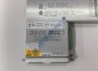
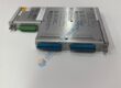
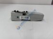
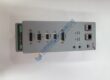
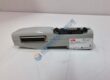
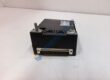
Product Core Brief
- Model: UNITROL 1010
- Part Number: 3BHE035301R1002
- ABB Type: UNS 0121A-Z, V1
- Series: UNITROL 1000
- Core Function: Regulates excitation and terminal voltage on indirectly excited synchronous machines.
- Type: Automatic voltage regulator (AVR) / excitation controller
- Key Specs: Up to 10 A continuous excitation current at 55 °C; IGBT power stage; Ethernet, USB, RS-485, and CAN interfaces
- Application: Synchronous generators and motors
- Condition: Verify supplier condition; request New Original (New Surplus) or Refurbished (tested)
- Availability: Legacy or revision-dependent stock; confirm hardware and firmware before purchase
Product Introduction
ABB UNITROL 1010, part number 3BHE035301R1002, is a digital automatic voltage regulator for excitation control on indirectly excited synchronous generators and motors. It supports AVR, field-current, reactive-power, and power-factor regulation modes.
The controller uses an IGBT power stage and delivers up to 10 A continuous excitation current at 55 °C, subject to the complete electrical rating and cooling conditions. It provides local display functions, USB configuration, Ethernet access, RS-485, CAN, analog I/O, and digital I/O. The standard unit operates at IP20, so panel installation requires suitable enclosure protection.
The ABB UNITROL 1010 user manual identifies this device as an AVR for synchronous machines and documents the IGBT power stage, IP20 casing, control interfaces, Modbus access, and excitation functions.
Some supplier listings state 10 A at 55 °C, CMT1000 Release 6.xxx, and firmware Release 6.320 for this part number. Treat Release 6.320 as supplier-provided information until the actual unit’s firmware screen or commissioning report confirms it.
Do not replace a UNITROL 1010 from the part number alone. Confirm the machine voltage, auxiliary supply method, excitation-current requirement, field voltage, current-transformer and potential-transformer ratios, communication interface, firmware release, parameter file, and cabinet wiring.
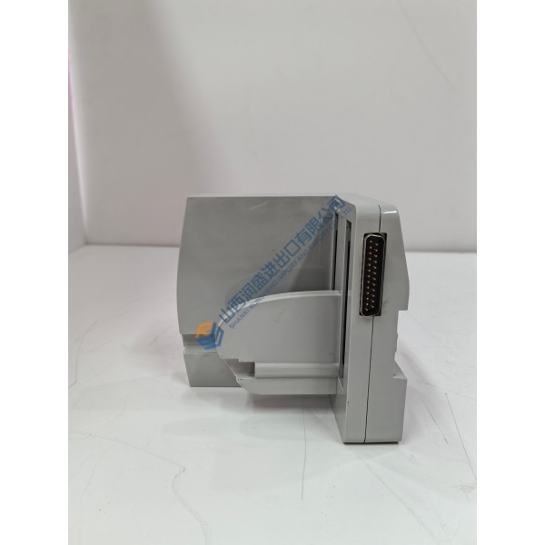
Installation & Configuration Guide
Phase 1—Pre-Installation — estimated 30 min
- Shut down the generator or motor and open the relevant circuit breakers.
- Isolate auxiliary supply, power-electronics supply, machine-voltage inputs, machine-current inputs, and excitation output.
- Follow the five electrical safety steps: disconnect completely, secure against reconnection, verify dead, ground and short-circuit where required, and protect against adjacent live parts.
- Wait at least 5 min for internal capacitors to discharge.
- Do not touch or disconnect the unit while the orange capacitor-warning LED remains active.
- Prepare a Fluke 115 multimeter, 500 V megohmmeter, insulated tools, ESD wrist strap, ESD mat, camera, cable labels, and laptop with the approved CMT1000 release.
- Export the current parameter file and save event records.
- Photograph all terminals, jumpers, RS-485 termination settings, CAN termination settings, Ethernet cable routing, and LED states.
- Record the existing firmware versions for DSP, MCU, and CMT1000 compatibility.