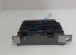
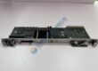
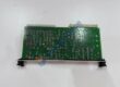
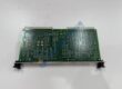
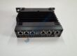
Product Core Brief
- Model: PMAC2-PCI (PMAC2 PCI)
- Brand: Delta Tau Data Systems (Omron Delta Tau)
- Series: PMAC2 Motion Controller Series
- Core Function: High-speed multi-axis trajectory generation, servo loop processing, and complex kinematic motion control.
- Product Type: PCI-Bus Motion Control Board
- Key Specs: Motorola DSP563xx Core | Up to 8 Axes Servo/Stepper Control | PCI Bus Interface Condition: New Original (New Surplus)
Product Introduction
Delta Tau PMAC2-PCI is a high-performance, multi-axis motion controller board engineered to plug directly into industrial PC PCI bus slots. Powered by a high-speed Motorola DSP, this processor handles trajectory generation, inverse kinematics, and sub-millisecond servo loop updates for complex CNC machinery, robotics, semiconductor equipment, and precision positioning stages.
This module delivers high flexibility across servo loop topologies, supporting analog ±10 V velocity/torque commands alongside pulse-and-direction digital outputs. Its architecture reduces calculation overhead on the host PC, ensuring deterministic real-time motion trajectory execution without risk of OS-induced timing jitter.
Quality Control & Inspection Process
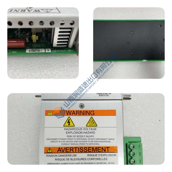
Surplus motion control hardware requires rigorous verification before installation in precision automated systems. Every unit undergoes a 5-step quality assurance workflow:
- Inbound Inspection: Verify origin documentation and check board serial numbers against OEM manufacturing registers. Visually inspect PCB traces, gold PCI edge connector fingers, and surface components for micro-cracks, mechanical strain, or solder degradation.
- Live Functional Testing: Install the card into an industrial PC test rig. Perform power-on self-tests (POST), run PEWIN32 PRO communications handshakes, and execute 8-axis interpolation and servo loop closure tests under load for over 24 hours.
- Electrical Testing: Conduct insulation resistance checks using a 500 V Megger (verifying >10 MΩ threshold) and test grounding continuity across all shield and chassis points.
- Firmware & Memory Verification: Read and record onboard DSP firmware builds (e.g., V1.940). Clear user registers, backup default option parameters, and confirm SRAM and Flash EEPROM write/erase integrity.
- Final QC & Packaging: Enclose the board in metallic anti-static shielding bags with fresh desiccant. Secure within dense anti-static foam framing inside a heavy-duty container stamped with a QC Passed seal.
Technical Pitfall & Installation Guide
Avoid these common integration errors during field replacement:
- Firmware Rev Mismatch: Running PEWIN32 PRO or Executive software compiled for newer firmware builds on a card with older DSP firmware can cause corrupted memory structures (P-variables and I-variables). Verify and document existing firmware builds before swapping modules.
- DIP Switch / Jumper Configuration: Incorrect E-bus termination jumper settings or base memory address switches will cause PCI bus enumeration failures (Error 13 / No Board Detected). Photograph and duplicate every jumper setting from the original board prior to insertion.
- Terminal / Pinout Incompatibility: Verify pinout maps on accessory breakout boards (such as ACC-24P or ACC-8E). Connecting encoder power lines to analog command channels will cause short circuits and permanently burn operational amplifiers.
- Power Supply Margin: High-frequency DSP processing cards require stable +5 VDC and +12 VDC rails from the host PC motherboard power supply. Voltage drops below 4.75 VDC cause unexpected DSP watchdog resets. Maintain a 20% power margin on the PC supply.
- ESD Protection: CMOS DSPs and array gate microprocessors on this board tolerate very low electrostatic discharges. Always wear a grounded anti-static wrist strap during all installation and wiring steps.