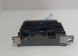
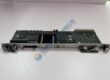
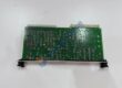
Product Core Brief
- Model: A3.SM.000-62DY
- Brand: KEB (Karl E. Brinkmann GmbH)
- Series: COMBIVERT A3 / SM Servo Series
- Core Function: Converts inverter drive signals into high-precision rotational mechanical output.
- Type: AC Synchronous Servo Motor Unit
- Key Specs: Permanent magnet design, integrated feedback encoder, industrial IP-rated enclosure
- Condition: New Original (New Surplus) — not refurbished
Product Introduction Struggling with unexpected positioning errors on your motion control axis? Deploying the KEB A3.SM.000-62DY servo motor unit resolves shaft sync drift inside tightly integrated COMBIVERT drive setups.
This motor executes fast dynamic speed profiles, holding exact torque curves up to nominal thermal limits. Operating this unit across demanding packaging or CNC equipment reduces axial positioning jitter to sub-millimeter tolerances.
Key Technical Specifications
- Manufacturer: KEB Automation KG
- Part Number: A3.SM.000-62DY
- Product Line: COMBIVERT Servo Series
- Motor Type: Permanent Magnet AC Synchronous Servo
- Nominal Voltage: 400 V AC / 480 V AC drive interface
- Cooling Method: Natural convection / Surface air-cooled
- Enclosure Protection: IP65 rating (excluding shaft output)
- Feedback System: Integrated rotary resolver / encoder assembly
- Mounting Style: Standard IEC flange configuration
- Operating Ambient: −20 °C to +40 °C
Installation & Configuration Guide
Phase 1 — Pre-Installation (est. 10 min) Shut off main circuit breakers feeding the drive inverter. Wait 5 full minutes for intermediate DC bus capacitors to discharge down to safety levels under 50 V DC. Gather your 5 mm hex keys, calibrated torque wrench, and Fluke 115 multimeter. Backup current parameter sets from the connected COMBIVERT inverter. Photograph current cable routing, terminal numbering, and earth grounding links.
Phase 2 — Removal (est. 5 min) Label power cables (U, V, W) and feedback lines clearly. Unbolt the encoder connector housing carefully without pulling directly on individual leads. Unfasten four flange mounting bolts using crosswise sequence. Pull the old motor straight off its gearhead box or mounting frame, checking for shaft keyway wear or oil seal leakage.
Phase 3 — Installation (est. 10 min) Equip your ESD wrist strap before touching exposed feedback pins. Verify part tags match: KEB A3.SM.000-62DY must replace like-for-like. Align keyway slot, seating flange flush against mechanical surface. Tighten mounting bolts to 9.5 N·m. Connect motor power leads, torqueing terminal screws to ~0.5 N·m. Secure shielding clamps onto ground rails to suppress EMC interference.
Phase 4 — Power-On & Testing (est. 15 min) Measure line voltage to verify 24 V DC control power sits within ±10%. Supply main power; verify drive display shows no overcurrent or feedback fault alerts. Open KEB COMBIVIS commissioning software. Load motor parameters, run manual jiggling commands at 100 rpm, and verify encoder pulse feedback counting up correctly. Execute full closed-loop sequence, running system continuous for 30 minutes while tracking housing temperature rise. Log swap details in maintenance journals.