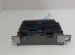
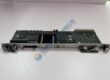
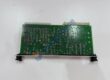
Product Core Brief
- Model: AAP3798102-00030
- Brand: CAMERON
- Series: Vantage / Maestro Compressor Control
- Core Function: Main logic processor for centrifugal compressor control panels
- Type: Processor / Control Module
- Key Specs: 100-240 VAC input; 2 A rating; digital output
- Condition: New Original (New Surplus) — not refurbished
Product Introduction
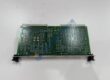
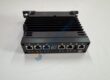
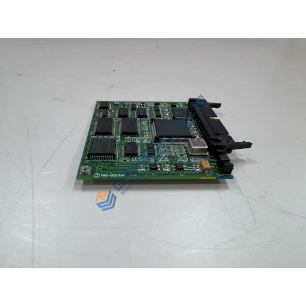
CAMERON AAP3798102-00030 sits at the core of many Vantage and Maestro compressor control panels. This processor module handles the main logic, digital outputs, and system sequencing for centrifugal compressors in industrial air or process gas service.
When the original board fails or a spare is needed, the unit restores panel function without a full system redesign. Typical installations see it run 100-240 VAC input at roughly 2 A, driving digital outputs for valves, alarms, and interlocks. Lead time and stock availability matter here — downtime on a compressor package costs far more than the module itself.
Key Technical Specifications
Verify exact pinout and firmware against your compressor serial number and original panel drawings. Specs above are drawn from series data for the AAP3798102 family; confirm with the OEM datasheet or your system documentation before ordering.
Installation & Configuration Guide
Phase 1 — Pre-Installation (est. 10 min)
De-energize the control panel and wait a full 5 minutes for residual charge to dissipate. Gather a Fluke 115 multimeter, ESD wrist strap, torque screwdriver, and camera. Export any existing control program if the panel still powers. Photograph every DIP switch, jumper, terminal block, and wire label before touching anything.
Phase 2 — Removal (est. 5 min)
Label every wire and connector. Release the module from its mounting. Pull it straight out perpendicular to the backplane or chassis. Inspect connector pins for bent or corroded contacts.
Phase 3 — Installation (est. 10 min)
Put on the ESD strap first. Confirm the part number matches AAP3798102-00030. Replicate the exact DIP/jumper settings from your photos. Seat the module firmly until the latch engages. Reconnect wiring at approximately 0.5 N·m. Run a pre-power checklist: correct voltage present, no shorts, ground continuity good.
Phase 4 — Power-On & Testing (est. 15 min)
Apply 100-240 VAC and verify supply within ±10 %. Watch the LEDs — green for RUN, red flash for ERR, amber for DIAG. Connect programming software if required, download or verify the program, then exercise digital outputs and one full control loop. Confirm stable operation for at least 30 minutes. Log the swap in the maintenance record. Test photos or video available on request.
Troubleshooting quick-reference:
- No communications → check cable, port, and power
- Steady ERR → firmware or configuration mismatch; verify version
- Download fails → cable integrity and software version