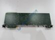
Product Core Brief
- Model: DS200SNPAH1ABA
- Brand: GE (General Electric)
- Series: LS2100 / Mark V Speedtronic / Drive Control
- Core Function: Provides isolated serial communication between DSPC motherboard and Series 90-30 PLC
- Type: Protocol Interface Daughterboard
- Key Specs: SNP protocol; RS-232C + isolated RS-485; VME rack mount
- Condition: New Original (New Surplus) — not refurbished
Product Introduction
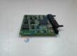
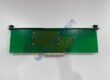
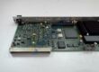
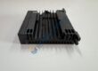
GE DS200SNPAH1ABA is the SNP Protocol Interface Daughterboard used on GE LS2100 static starter and related Mark V / drive control systems. It mounts on the DSPC Digital Signal Processor Control motherboard and creates the serial link to a Series 90-30 PLC.
The board supports both RS-232C for short runs and isolated RS-485 for longer or multi-drop links, all running the Series Ninety Protocol. When a PLC-based LCI needs reliable communication to the drive controller, this unit restores the link without forcing a full system redesign. Genuine stock is limited — verify your exact revision before ordering.
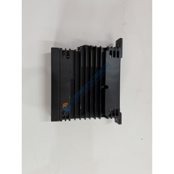
Confirm exact revision and connector pinout against your cabinet drawings and the GEI-100226 manual. Specs reflect series documentation; always verify with the OEM datasheet for your installation.
Installation & Configuration Guide
Phase 1 — Pre-Installation (est. 10 min)
De-energize the entire control cabinet and wait a full 5 minutes for residual charge to dissipate. Tools required: Fluke 115 multimeter, ESD wrist strap, torque driver, camera. Export any existing configuration if the DSPC still powers. Photograph every jumper, connector, and wire label on the existing daughterboard and motherboard.
Phase 2 — Removal (est. 5 min)
Label every cable. Release the daughterboard from its mounting on the DSPC. Pull it straight out perpendicular to the motherboard. Inspect the DSPC connectors and VME backplane pins for bent or corroded contacts.
Phase 3 — Installation (est. 10 min)
Put on the ESD strap first. Verify the part number matches DS200SNPAH1ABA. Replicate the exact protocol selection setting (1 = SNP enabled) and any jumpers from your photos. Seat the board firmly until fully engaged. Reconnect cables. Run a pre-power checklist: correct supply present, no shorts, ground continuity good.
Phase 4 — Power-On & Testing (est. 15 min)
Apply control power and verify supply voltage. Observe status LEDs if present. Establish communication with the Series 90-30 PLC and confirm SNP data exchange. Exercise one full control or status loop. Confirm stable operation for at least 30 minutes. Log the swap in the maintenance record. Test photos or video available on request.
Troubleshooting quick-reference:
- No communications → check protocol selection switch, cable, and RS-485 termination
- ERR or no link → firmware or SNP version mismatch; verify Series 90-30 configuration
- Intermittent data → inspect isolation and cable shielding