Product Core Brief
- Model: CMA132 (3DDE300412)
- Brand: ABB
- Series: Generator Relay Terminal
- Core Function: Provides secure terminal connections for generator relay signals
- Type: Terminal Board / Relay Interface
- Key Specs: 16 screw terminals; 690 V AC / 10 A; IP20
- Condition: New Original (New Surplus) — not refurbished
Product Introduction
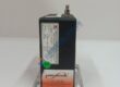
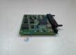
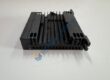
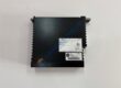
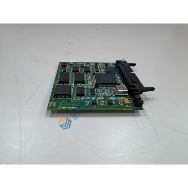
ABB CMA132 is a generator relay terminal board built for industrial control panels that need clean, labeled connections for start, stop, and fault signals. The board routes these critical signals with screw terminals rated for 690 V AC and 10 A.
In generator or turbine packages the unit replaces a failed or missing terminal board without redesigning the entire relay interface. Clear labeling and compact 100 × 100 × 25 mm form factor keep installation straightforward. Stock of genuine units remains limited — order early if your panel is down.
Verify exact wiring against your generator control drawings. Data above is taken from series documentation; always cross-check the OEM datasheet for your specific installation.
Installation & Configuration Guide
Phase 1 — Pre-Installation (est. 10 min)
De-energize the panel and wait a full 5 minutes for residual voltage to drop. Tools needed: Fluke 115 multimeter, ESD wrist strap, torque screwdriver, camera. Photograph every existing wire label, terminal position, and any jumpers before disconnecting anything.
Phase 2 — Removal (est. 5 min)
Label every conductor. Release the board from its DIN-rail clips. Pull it straight out. Inspect the rail and adjacent connectors for damage or corrosion.
Phase 3 — Installation (est. 10 min)
Attach the ESD strap. Confirm the part number matches CMA132. Seat the board firmly on the DIN rail until the latch clicks. Reconnect wires to the correct screw terminals at approximately 0.5–0.6 N·m. Run a pre-power checklist: correct voltage present, no shorts, ground continuity good.
Phase 4 — Power-On & Testing (est. 15 min)
Apply control power and verify supply voltage. Observe any status indicators. Exercise start, stop, and fault signal paths with a multimeter or the plant control system. Confirm stable operation for at least 30 minutes. Log the swap in the maintenance record. Test photos or video available on request.
Troubleshooting quick-reference:
- No signal continuity → check terminal torque and wire seating
- Intermittent contact → inspect for oxidation or loose screws
- Wrong polarity → re-verify labeling against the original photos