Product Core Brief
- Model: DS2020DACAG2
- Brand: GE (General Electric)
- Series: EX2100 Excitation / Mark VIe
- Core Function: Converts 115/230 VAC to regulated 125 VDC for control power
- Type: AC-DC Power Conversion Assembly (DACA)
- Key Specs: 1000 W output; 9.5 A single / up to 16.5 A paralleled; replaceable capacitors
- Condition: New Original (New Surplus) — not refurbished
Product Introduction
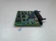
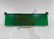
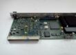
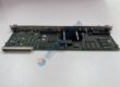
GE DS2020DACAG2 is the AC-to-DC power conversion assembly used in EX2100 excitation and Mark VIe turbine control systems. It takes 115 or 230 VAC input and delivers a stable 125 VDC bus for the control electronics.
The unit replaces the earlier DACAG1 as a fully backward-compatible drop-in. It also supplies local energy storage that extends ride-through during brief control-power interruptions. Parallel operation of multiple modules raises available current when the load demands it. Genuine stock moves quickly — confirm your input voltage selection before ordering.
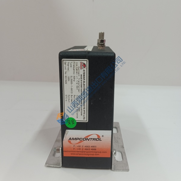
Verify input jumper setting (JTX1 = 115 V / JTX2 = 230 V) and exact cabinet wiring against the OEM drawings. Specs are taken from series documentation; always cross-check the official GE manuals for your installation.
Installation & Configuration Guide
Phase 1 — Pre-Installation (est. 10 min)
De-energize the entire control cabinet and wait a full 5 minutes for residual charge to dissipate. Tools needed: Fluke 115 multimeter, ESD wrist strap, torque driver, camera. Photograph the existing module’s connector orientation, any jumpers, and the PDM (Power Distribution Module) wiring before removal.
Phase 2 — Removal (est. 5 min)
Label every conductor on the JZ connector. Release the mounting hardware. Pull the assembly straight out. Inspect the mating connector and surrounding bus for damage or corrosion.
Phase 3 — Installation (est. 10 min)
Attach the ESD strap. Confirm the part number matches DS2020DACAG2. Set the internal input selector cable to JTX1 (115 V) or JTX2 (230 V) exactly as the original. Seat the module firmly and secure the mounting points. Reconnect the 12-position JZ connector. Run a pre-power checklist: correct AC present, no shorts, ground continuity good.
Phase 4 — Power-On & Testing (est. 15 min)
Apply AC input and verify output voltage is within the expected 125 VDC range. Observe status LEDs if present. Measure load current under normal and peak conditions. Confirm stable operation for at least 30 minutes, including a simulated brief power interruption to check ride-through. Log the swap in the maintenance record. Test photos or video available on request.
Troubleshooting quick-reference:
- No DC output → check input selector cable position and AC supply
- Low voltage under load → verify paralleling connections and capacitor health
- Over-temperature or trip → confirm free-convection airflow and ambient limits