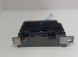
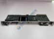
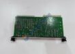
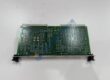
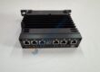
Product Core Brief
- Model: HE65S 206-00212
- Brand: TR Electronic
- Series: HE65S Absolute Rotary Encoder
- Core Function: Provides absolute single-turn position feedback via optical sensing
- Type: Absolute Rotary Encoder
- Key Specs: 65 mm body; solid shaft; optical; 11–27 VDC typical
- Condition: New Original (New Surplus) — not refurbished
Product Introduction
TR ELECTRONIC HE65S 206-00212 is a compact absolute rotary encoder from the HE65S series. The 65 mm body houses an optical single-turn sensing system that delivers absolute position data without requiring a home cycle after power loss.
This unit is commonly used on machine axes, rotary tables, and packaging equipment where reliable absolute feedback is required. Standard flange and solid-shaft options allow direct mechanical interchange with many existing HE65S installations. Verify the exact interface and resolution against your original part before ordering.
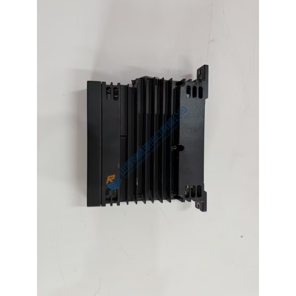
Confirm exact resolution, output code (binary/Gray), interface (parallel, SSI, etc.), and connector orientation against the original encoder label or TR Electronic documentation. Specs above reflect the HE65S family; the precise 206-00212 configuration must be verified with the OEM datasheet.
Installation & Configuration Guide
Phase 1 — Pre-Installation (est. 10 min)
De-energize the machine axis and wait a full 5 minutes for residual voltage to drop. Tools required: Fluke 115 multimeter, ESD wrist strap, torque driver, camera. Photograph the existing encoder’s shaft coupling, flange orientation, cable routing, and any alignment marks before removal.
Phase 2 — Removal (est. 5 min)
Label every conductor. Release the coupling and flange fasteners. Pull the encoder straight off the shaft. Inspect the shaft end, coupling, and mounting surface for wear or damage.
Phase 3 — Installation (est. 10 min)
Attach the ESD strap. Confirm the part number matches HE65S 206-00212. Align the new encoder to the same flange orientation and shaft position as the original. Seat the coupling and torque fasteners to the manufacturer’s values. Reconnect the cable. Run a pre-power checklist: correct supply voltage present, polarity correct, no shorts.
Phase 4 — Power-On & Testing (est. 15 min)
Apply 11–27 VDC and verify the encoder powers without fault. Check absolute position reading against a known reference point. Rotate the axis through a full revolution and confirm continuous absolute data. Confirm stable operation for at least 30 minutes under normal load. Log the swap in the maintenance record. Test photos or video available on request.
Troubleshooting quick-reference:
- No position data → check supply voltage, polarity, and cable continuity
- Incorrect absolute value → verify counting direction and interface settings
- Intermittent signal → inspect coupling alignment and connector seating