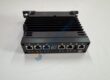
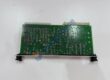
Product Core Brief
- Model: KUC711AE101 (Part Number: 3BHB004661R0101)
- Brand: ABB
- Series: AC800PEC / UNITROL Series
- Core Function: Processes high-speed control loops and manages communication across excitation and converter systems.
- Type: Central Processor Module
- Key Specs: High-performance processing core, optical fiber interface support, robust backplane integration
- Condition: New Original (New Surplus) — not refurbished
Product Introduction Tired of processing delays disrupting heavy power electronics control loops? Deploying the ABB KUC711AE101 3BHB004661R0101 processor module stabilizes fast excitation and converter logic across demanding AC800PEC control architectures.
This module handles multi-variable control algorithms, driving fast signal throughput across optical and backplane communication links. Operating this unit inside power generation or large drive systems cuts control loop execution down to sub-millisecond ranges.
Key Technical Specifications
- Manufacturer: ABB
- Module Type: KUC711AE101
- Part Number: 3BHB004661R0101
- Product Family: AC800PEC / UNITROL 6000
- Processor Architecture: High-speed 32-bit RISC / DSP processing core
- Operating Supply Voltage: 24 V DC system backplane distribution
- Communication Interfaces: Fast Ethernet, optical fiber links, system bus
- Mounting Style: Dedicated AC800PEC rack frame slot
- Operating Ambient: 0 °C to +55 °C
- Storage Temperature: −40 °C to +70 °C
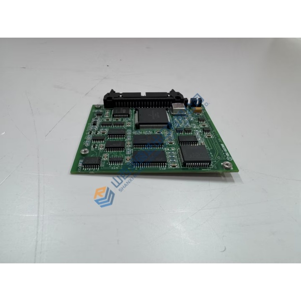
Installation & Configuration Guide
Phase 1 — Pre-Installation (est. 10 min) De-energize main supply breakers feeding the AC800PEC rack frame. Wait 5 full minutes for intermediate DC bus capacitors in connected power units to drain down safely below 50 V DC. Gather your ESD wrist strap, slot screwdrivers, and a Fluke 115 multimeter. Export existing system software parameters from your engineering tool. Photograph fiber optic routing, module slot placement, and DIP switch locations before unmounting hardware.
Phase 2 — Removal (est. 5 min) Disconnect optical cables carefully by holding connector bodies rather than pulling delicate fibers. Label and unplug Ethernet patch leads and power connectors. Unscrew top and bottom rack retention fasteners. Pull the old unit straight out along guide rails, protecting rear multi-pin connectors from lateral bending stress.
Phase 3 — Installation (est. 10 min) Equip your ESD wrist strap before opening protective static shielding bags. Verify module labels confirm the ABB KUC711AE101 3BHB004661R0101 matches your target drawing requirements. Replicate DIP switch configuration blocks from the original unit onto replacement hardware. Slide the replacement module smoothly along rack guides until backplane connectors seat completely, then torque retention screws to ~0.5 N·m.
Phase 4 — Power-On & Testing (est. 15 min) Apply system power; check voltage levels at rack terminals to verify 24 V DC ±10% tolerances. Observe diagnostic LEDs during bootup: verify RUN indicator lights solid green while ERR indicators stay dark. Connect via Control Builder software, execute communication handshake checks, and run full signal simulation across connected control loops. Run continuous monitoring for 30 minutes while tracking thermal stability, then record hardware replacement details in maintenance logs.
Troubleshooting Quick-Reference
- ERR LED Solid Red: Firmware mismatch or internal self-test failure; perform system reset or reload firmware.
- No Comm / Link LED Off: Inspect fiber optic connectors for dust, cracked glass, or tight bend radiuses.
- Boot Failure: Check 24 V DC power bus voltage level and verify proper backplane card seating.