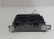
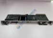
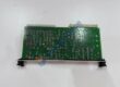
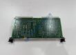
Product Core Brief
- Model: 0190-25290
- Brand: Applied Materials (AMAT)
- Series: Semiconductor Process Equipment / Endura & Centura Platform
- Core Function: Regulates tool telemetry signals and conditions internal power feeds across vacuum chamber assemblies.
- Type: Tool Control / Distribution Interface Module
- Key Specs: Multi-pin interconnect assembly, high-noise-immunity PCB layout, cleanroom-compatible enclosure
- Condition: New Original (New Surplus) — not refurbished
Product Introduction Tired of intermittent sensor faults causing unpredicted wafer aborts inside your vacuum chambers? Deploying the AMAT 0190-25290 interface module restores stable signal routing across sensitive Applied Materials processing platforms.
This board conditions critical tool telemetry, passing high-integrity control signals back to central system controllers. Operating this component inside high-vacuum etch or deposition tools drops signal processing latency to sub-millisecond ranges.
Key Technical Specifications
- Manufacturer: Applied Materials Inc. (AMAT)
- Part Number: 0190-25290
- Equipment Line: Endura / Centura / Producer Semiconductor Tools
- Module Type: Signal Distribution & Interface PCB Assembly
- Operating Supply: 24 V DC / ±15 V DC internal distribution power
- Interface Connectors: High-density multi-pin card edge / pin headers
- Mounting Style: Internal electronics rack slot assembly
- Cleanroom Class: ISO Class 10 / Class 100 compatible
- Operating Ambient: +15 °C to +40 °C
- Storage Temperature: −10 °C to +60 °C
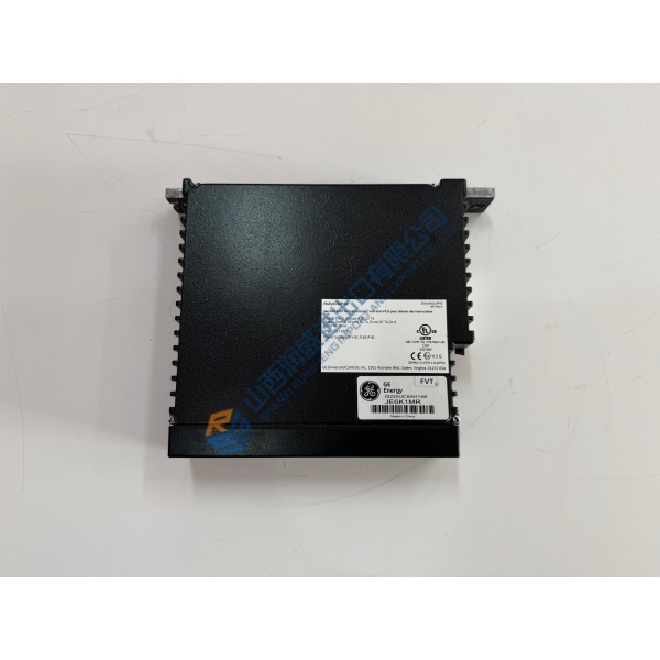
Installation & Configuration Guide
Phase 1 — Pre-Installation (est. 10 min) De-energize main breaker panels feeding the tool electronics bay. Lock out and tag out power sources according to cleanroom safety protocols. Wait 5 full minutes for internal capacitive power supplies to drain down safely below 50 V DC. Gather your ESD wrist strap, slot screwdrivers, and a Fluke 115 multimeter. Export existing tool configuration files from the operator workstation. Photograph card placement, cable harness routing, and jumper positions before unmounting hardware.
Phase 2 — Removal (est. 5 min) Disconnect high-density interface cables carefully by loosening thumb screws or side latches rather than pulling directly on wiring harnesses. Unscrew card cage retention fasteners securing the assembly. Pull the old module straight out along guide tracks, protecting gold card-edge pins from scraping against the chassis.
Phase 3 — Installation (est. 10 min) Put on your ESD wrist strap before handling replacement parts inside the cleanroom. Verify hardware tags confirm the AMAT 0190-25290 matches your system bill of materials exactly. Replicate jumper blocks from the original board onto replacement hardware. Slide the new board along card cage guide tracks until rear multi-pin connectors seat completely, then torque retention screws to ~0.5 N·m.
Phase 4 — Power-On & Testing (est. 15 min) Reapply tool electronics power; verify DC supply rails at distribution terminals sit within 24 V DC ±10% tolerances. Observe diagnostic LEDs on board edge: confirm power indicators show solid green while fault indicators remain unlit. Connect via system diagnostic software, execute signal loop verification tests, and run a simulated wafer processing cycle. Monitor continuous operation for 30 minutes, checking tool event logs before entering hardware change details in fab maintenance records.