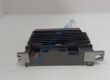
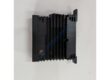
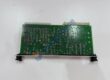
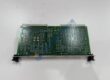
Product Core Brief
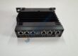
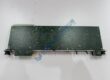
- Model: PDX 900-2V (P/N: 3156024-110; AMAT P/N: 0190-08677-002)
- Brand: Advanced Energy (AE)
- Series: PDX Series RF Plasma Generators
- Core Function: 900 W, 350 kHz RF power supply for semiconductor plasma etch/deposition and sputtering tools.
- Type: RF Plasma Generator / Power Supply
- Key Specs: 900 W max output; 350 kHz (±50 kHz tuning); 850 V max output voltage; 220/240 VAC, 20 A, 1-phase input; Type N RF output connector
- Condition: Refurbished (tested) — not new
⚠️ Note: Multiple part number variants exist (3156024-110, -110C, -132, -132C, -030E). Verify exact P/N and firmware revision before ordering.ebay+2
Product Introduction
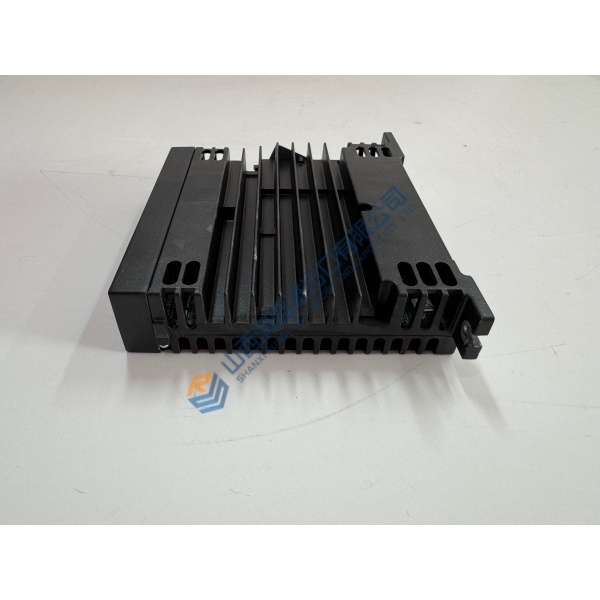
In semiconductor fab lines running Applied Materials (AMAT) etch or deposition chambers, the Advanced Energy PDX 900-2V (3156024-110) shows up repeatedly as the RF plasma generator that drives 350 kHz process plasmas at up to 900 W. It’s a 19-inch rack-mount RF power supply—designed to slot into AMAT and other OEM tool racks and deliver stable, regulated RF power for reactive ion etching, RF sputtering, and DC sputtering with RF bias.ebay+2
What sets this unit apart isn’t just power—it’s regulation accuracy and load matching. Forward power regulation holds at ±1% of setpoint (or ±2 W, whichever is greater), reflected power tolerance hits 250 W max, and the internal 7-step load-matching transformer covers 25–125 Ω loads. Harmonics land >45 dB below fundamental at 900 W/350 kHz into 50 Ω, and the unit supports remote on/off and voltage margin control via TTL (2–5 V) or analog (0–10 V). Honestly, if your spec calls for 350 kHz, 900 W plasma with tight regulation and AMAT tool compatibility, this is the generator you spec. Just verify the part number suffix and firmware—more on that below.
Installation & Configuration Guide
Phase 1 — Pre-Installation (est. 10 min)
- De-energize RF generator and process tool; wait 5 min for capacitor discharge.
- Tools: ESD wrist strap, insulated screwdrivers, torque driver (0.5 N·m), multimeter (Fluke 115 or equivalent), RF power meter/dummy load (optional), camera/phone.
- Backup tasks: Export current generator settings (if replacing), photograph control connector wiring (25-pin D-sub), DIP switches, jumper settings, and rack layout. Record existing firmware revision from front panel or remote interface.
Phase 2 — Removal (est. 5 min)
- Label all AC input, RF output (Type N), and control cables before disconnecting.
- Remove rack-mount screws; slide module out perpendicular to rack rails.
- Inspect AC input connector (Hubble/IEC) and RF output connector for bent pins or corrosion—critical on high-cycle tools.
Phase 3 — Installation (est. 10 min)
- Ground yourself (ESD strap + mat). Verify part number matches order (3156024-110 vs. -132, etc.).
- Replicate control wiring from photos (especially remote on/off TTL, margin voltage, interlock pins).
- Seat module until rack ears align; secure with M6 rack screws (~0.5 N·m torque).
- Run pre-power checklist: AC input voltage 220/240 VAC ±10%, RF load connected (dummy load or chamber), cooling airflow unobstructed.
Phase 4 — Power-On & Testing (est. 15 min)
- Apply power; observe front-panel LEDs (AC OK green, DC OK green, FAULT red).
- Connect via 25-pin D-sub or front-panel controls; verify remote on/off (TTL 2–5 V = RUN).
- Run functional test: ramp RF power from 8 W to 900 W into dummy load, monitor forward/reflected power, verify regulation (±1% of setpoint).
- Confirm stable operation for >30 min at 900 W; log swap in maintenance record with firmware revision and control wiring diagram.