Description
Product Introduction
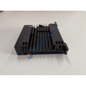
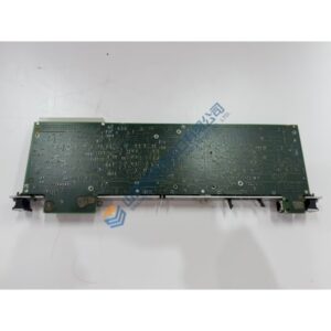
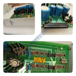
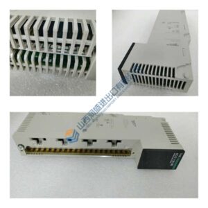
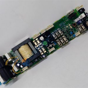
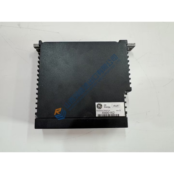
A speed governor trip on your mechanical drive steam turbine brings critical process pumps and compressors to an immediate standstill. The WOODWARD 8200-1300 Peak15 governor delivers reliable speed control, load regulation, and safety limiting across harsh industrial environments. Built in an IP20 industrial enclosure, it mounts directly into control cabinets without requiring special mounting brackets or backplane adapters.
In field deployments across power generation, oil and gas, and chemical processing facilities, this controller maintains tight speed stability and sub-second response times during rapid load shifts. The WOODWARD 8200-1300 integrates smoothly into plant SCADA systems via Modbus communications to keep rotating equipment running safely. Listed prices serve as a baseline market reference; actual costs depend on global surplus availability and current lead times. Contact our procurement team directly to request an exact quote.
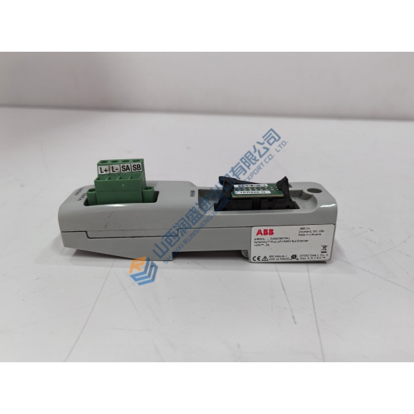
Installation & Configuration Guide
Phase 1 — Pre-Installation (est. 10 min)
Safely trip the steam turbine, close main steam inlet valves, and verify zero shaft rotation before working on the control panel. De-energize the 24 V DC control power bus. Assemble a precision flathead screwdriver, torque driver, ESD grounding wrist strap, and a digital multimeter. Backup active control parameters, speed setpoints, and PID tuning values using Woodward ControlAssistant software or the front display panel. Take clear photos of all terminal block wiring and jumper settings on the active WOODWARD 8200-1300 unit.
Phase 2 — Removal (est. 5 min)
Label every wire tag (MPU lines, actuator outputs, power, relay contacts) before disconnecting them. Unplug the screw terminal plugs by loosening their side locking fasteners. Remove the panel mounting screws or release the DIN-rail retaining latch on the base of the enclosure. Lift the unit off the mounting panel. Inspect the enclosure and surrounding wiring channels for dust, moisture, or heat damage.
Phase 3 — Installation (est. 10 min)
Put on your ESD wrist strap and bond its grounding lead to the cabinet enclosure. Remove the replacement WOODWARD 8200-1300 from its anti-static packaging. Check the side label and serial number against your bill of materials. Secure the unit onto the DIN rail or panel surface, tightening mounting hardware to ~0.8 N·m. Reconnect terminal block plugs according to your wire tags, torquing terminal screws to ~0.4 N·m. Verify actuator polarity and MPU cable shielding before proceeding.
Phase 4 — Power-On & Testing (est. 15 min)
Measure incoming DC power voltage — verify 24 V DC nominal before turning on the power breaker. Apply power. Observe the LED boot sequence: POWER LED turns steady green, FAULT LED clears following internal self-test routines, and the display initializes. Load the saved parameter file using Woodward ControlAssistant. Verify MPU frequency readings, test overspeed trip logic, and stroke the actuator valve from 0% to 100% to confirm linear movement. Monitor closed-loop speed stability during turbine startup before returning the system to operational service. Log all replacement details in your turbine maintenance record.
Quick Troubleshooting Reference
- Overspeed Trip / FAULT Light On: Loss of MPU speed signal, incorrect overspeed setpoint, or actuator feedback fault; verify MPU AC voltage (>1.5 V RMS at cranking speed).
- Speed Hunting / Unstable Control: PID gain set too high or mechanical play in valve linkage; recalibrate governor dynamics (Proportional/Integral terms) and check valve linkage joints.
- No Modbus Communication: Check RS-485 polarity (A/B lines), verify node address and baud rate in settings, and ensure line termination is enabled at line ends.