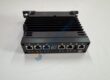
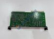
Product Core Brief
- Model: PPD517A3021 (Order Code: 3BHE041576R3021)
- Brand: ABB
- Series: UNITROL 1000 / 6000 / AC 800PEC Excitation Control Platform
- Core Function: Core processor module for synchronous generator excitation and AVR control.
- Type: Excitation Controller / Processor Module
- Key Specs: 24 V DC supply (18–30 VDC); high-speed RISC processor; fiber optic + Ethernet + RS-485 comms; −5 °C to +70 °C operating temp; IP20
- Condition: New Original (New Surplus) — not refurbished
⚠️ Note: Multiple firmware/hardware revisions exist (R3011, R3021, R3023, etc.). Verify exact order code and firmware before ordering.
Product Introduction
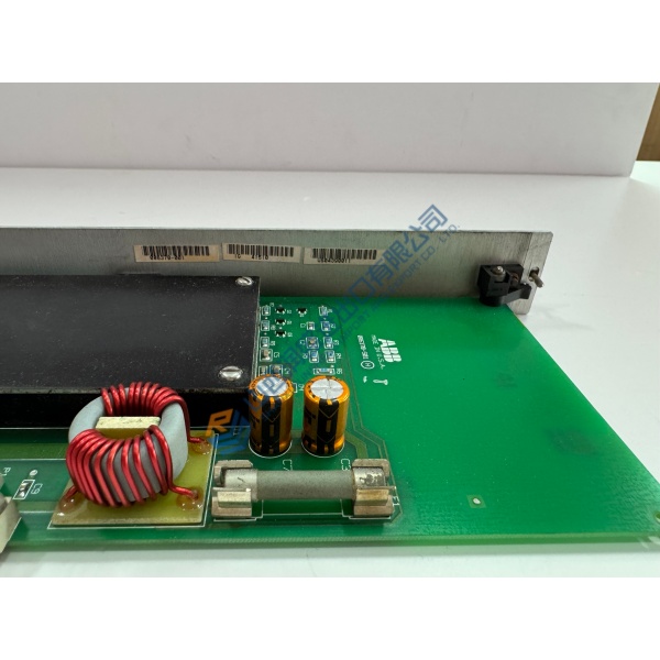
In ABB UNITROL 1000, 6000, and AC 800PEC excitation systems, the ABB PPD517A3021 (3BHE041576R3021) shows up as the core processor that runs AVR logic, reactive power control, and grid stability functions for synchronous generators. It’s the brain of the excitation rack—executing control algorithms at sub-millisecond rates and coordinating with power bridges, I/O modules, and SCADA via fiber optic, Ethernet, and RS-485 links.rsdcsplc+2
What sets this module apart isn’t just CPU speed—it’s deterministic timing and fieldbus stability. The PPD517A3021 holds generator terminal voltage within ±0.25% to ±0.5% accuracy, responds to step changes in <10 ms, and supports redundancy (power, network, control) for high-availability plants. Firmware version ≥1.40N is required to activate all protection functions, and the unit pairs with S800 I/O racks and AC800M controllers for full DCS integration. Honestly, if your spec calls for hydro, thermal, or gas turbine excitation with tight voltage regulation and ABB tool compatibility, this is the processor you spec. Just verify the order code suffix and firmware—more on that below.
Installation & Configuration Guide
Phase 1 — Pre-Installation (est. 10 min)
- De-energize excitation rack; wait 5 min for capacitor discharge.
- Tools: ESD wrist strap, insulated screwdrivers, torque driver (0.5 N·m), multimeter (Fluke 115 or equivalent), fiber optic cleaning kit, camera/phone.
- Backup tasks: Export current excitation configuration via ABB Control Builder or HMI, photograph fiber optic cable routing, Ethernet/RS-485 wiring, DIP switches, jumper settings, and rack layout. Record existing firmware version from front panel or diagnostic port.
Phase 2 — Removal (est. 5 min)
- Label all fiber optic cables (TX/RX), Ethernet, RS-485, and power connections before disconnecting.
- Release module latches or DIN rail clips; pull module perpendicular to backplane.
- Inspect backplane connector pins and fiber optic ports for bent pins, corrosion, or contamination—critical on high-cycle plants.
Phase 3 — Installation (est. 10 min)
- Ground yourself (ESD strap + mat). Verify order code matches order (3BHE041576R3021 vs. -R3011, etc.).
- Replicate jumper/DIP config from photos (especially communication mode, redundancy settings).
- Seat module until latch clicks; reconnect fiber optic cables (clean connectors first), Ethernet, RS-485, and 24 V DC supply.
- Run pre-power checklist: 24 V DC within tolerance (18–30 VDC), fiber optic link integrity (no sharp bends), cooling airflow unobstructed.
Phase 4 — Power-On & Testing (est. 15 min)
- Apply power; observe front-panel LEDs (RUN green, FAULT red, COMM amber).
- Connect via Ethernet or RS-485 to ABB Control Builder; verify communication handshake.
- Download/verify configuration; run functional test on AVR logic, reactive power control, and protection functions (overvoltage, undervoltage, overcurrent).
- Confirm stable operation for >30 min in automatic mode; log swap in maintenance record with firmware version and configuration backup.