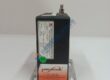
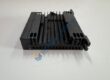
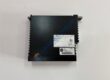
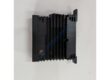
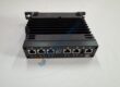
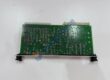
Product Core Brief
- Model: 5SHY3545L0009 (Product ID: 3BHB013085R0001)
- Brand: ABB
- Series: 5SHY HiPak IGCT Family
- Core Function: High-voltage, high-power asymmetric IGCT module for medium-voltage drives and power converters.
- Type: IGCT (Integrated Gate-Commutated Thyristor) Power Module
- Key Specs: 4500 V blocking voltage; 3500 A continuous current; 6000 A (10 ms) surge; −40 °C to +125 °C junction; press-pack HiPak with integrated gate driver
- Condition: New Original (New Surplus) — not refurbished
⚠️ Note: Multiple hardware/firmware revisions exist (L0004, L0009, L0013, etc.). Verify exact part number and gate driver compatibility before ordering.rsmodules+2
Product Introduction
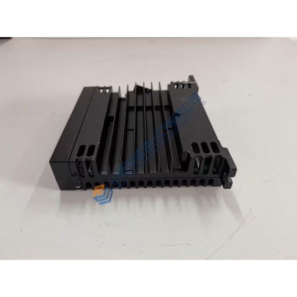
In ABB ACS 6000, ACS 5000, and other medium-voltage drive platforms, the ABB 5SHY3545L0009 (3BHB013085R0001) shows up as the core power switching device that handles 4.5 kV / 3500 A loads in mining, metallurgy, and heavy-duty industrial applications. It’s a press-pack HiPak IGCT module—integrating the IGCT chip, gate drive circuit, and freewheeling diode into a single low-stray-inductance unit for three-level medium-voltage topologies.rsmodules+2
What sets this module apart isn’t just voltage/current rating—it’s switching speed and conduction loss. Turn-on/turn-off times land at <10 μs (some sources cite ≤4.0 μs / ≤7.5 μs), on-state voltage drop holds at ≤1.9 V @ 3500 A, and total conduction loss stays under 2.5%. The unit supports forced liquid cooling (10–14 L/min deionized water/glycol) or external heatsink mounting, and pairs with ABB GVC750BE101 (v1.8+) or GVC736CE101 (v2.0+) gate drivers. Honestly, if your spec calls for 300 kVA to 10 MVA converter duty without series/parallel stacking, this is the IGCT you spec. Just verify the part number suffix and gate driver version—more on that below.
Installation & Configuration Guide
Phase 1 — Pre-Installation (est. 15 min)
- De-energize converter; apply Lock-Out/Tag-Out (LOTO) procedures.
- Wait 5 min for DC bus capacitor discharge; verify stored energy capacitors are below safe voltage (<50 V DC).
- Tools: ESD wrist strap, insulated screwdrivers, torque wrench (calibrated), thermal paste (if required), fiber-optic cleaning kit, multimeter (Fluke 115 or equivalent), camera/phone.
- Backup tasks: Record converter fault history, photograph all power busbar connections, label every gate driver cable, and note associated gate driver module and cooling assembly.
Phase 2 — Removal (est. 15–20 min)
- Remove converter access panels.
- Disconnect fiber-optic or gate-drive connections first.
- Remove power busbars in specified sequence (document torque values).
- Loosen mounting hardware evenly (cross-pattern for press-pack).
- Lift the IGCT module carefully—avoid bending leads or stressing the ceramic housing.
Phase 3 — Installation (est. 20 min)
- Verify part number is 5SHY3545L0009 / 3BHB013085R0001.
- Clean all mounting surfaces thoroughly (isopropyl alcohol, lint-free cloth).
- Install module using ABB’s specified clamping sequence (cross-pattern, incremental torque).
- Apply correct tightening torque (refer to ABB mechanical spec—typically 8–12 N·m for M6 bolts).
- Reconnect gate-drive wiring (fiber-optic polarity: TX→RX, RX→TX).
- Reinstall power busbars; apply anti-oxidation compound on copper surfaces.
- Confirm all insulation barriers are correctly positioned.
Phase 4 — Power-Up & Functional Testing (est. 20–30 min)
- Measure insulation resistance before energizing (>100 MΩ @ 4000 V DC).
- Apply auxiliary control power first (24 V DC gate supply).
- Verify gate driver diagnostics (no faults, fiber link OK).
- Power the converter gradually; monitor DC-link voltage ramp.
- Check switching status (all IGCTs firing in sequence).
- Monitor heatsink temperature (rise <40 °C above ambient at 50% load).
- Perform controlled load test (10% → 50% → 100% in steps, 5 min per step).
- Log swap in maintenance record with part number, gate driver version, and torque values.