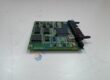
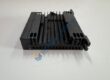
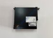
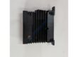
Product Core Brief
- Model: UF C912 A101 (Order Code: 3BHE039426R0101)
- Brand: ABB
- Series: ACS 2000 / ACS 6000 Medium-Voltage Drive Spare Parts
- Core Function: Emitter Output Interface (EOI) protection board for IGCT gate drive monitoring.
- Type: Protection Board / Drive Control Spare Part
- Key Specs: 24 V DC auxiliary supply (±20%); 8 digital I/O channels; fiber optic gate signal interface; 0 °C to +55 °C operating temp; IP20
- Condition: New Original (New Surplus) — not refurbished
⚠️ Obsolete Model – Limited Stock Available. For ACS 2000, 3BHE039426R0111 (UF C912 A111) is a 1-to-1 replacement and can be used instead of 3BHE039426R0101.vogiauto+2
Product Introduction
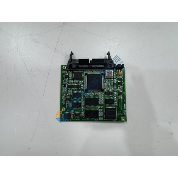
In ABB ACS 2000 and ACS 6000 medium-voltage drive systems, the ABB UF C912 A101 (3BHE039426R0101) shows up as the EOI (Emitter Output Interface) protection board that monitors gate drive signals and protection feedback between IGCT power modules and the drive control unit. It’s a compact PCB assembly—sitting between the gate driver and main controller to catch overcurrent, overvoltage, and overtemperature faults before they cascade into converter trips.vogiauto+2
What sets this board apart isn’t complexity—it’s deterministic fault response. The UF C912 A101 reacts to gate driver faults in <10 μs, isolates emitter output signals with 1500 V AC isolation, and supports 8 configurable digital I/O channels for status and alarm signaling. It pairs with GVC750BE101 or GVC736CE101 gate drivers and the 5SHY3545L0009 IGCT family, and integrates into ACS 2000/6000 drive racks without firmware changes. Honestly, if your spec calls for medium-voltage drive sustainment without full retrofit, this is the protection board you stock. Just verify the order code suffix and drive serial number—more on that below.
Installation & Configuration Guide
Phase 1 — Pre-Installation (est. 10 min)
- De-energize drive system; apply Lock-Out/Tag-Out (LOTO) procedures.
- Wait 5 min for DC bus capacitor discharge; verify stored energy capacitors are below safe voltage (<50 V DC).
- Tools: ESD wrist strap, insulated screwdrivers, torque driver (0.5 N·m), multimeter (Fluke 115 or equivalent), fiber optic cleaning kit, camera/phone.
- Backup tasks: Record drive fault history, photograph all gate driver fiber optic cables, label every EOI board connection, and note associated IGCT module and gate driver version.
Phase 2 — Removal (est. 5 min)
- Remove converter access panels.
- Disconnect fiber-optic gate drive connections first (TX/RX labeling).
- Remove control wiring (24 V DC DI/DO, Ethernet, RS-485) in documented sequence.
- Release module latches or DIN rail clips; pull board perpendicular to backplane.
- Inspect backplane connector pins and fiber optic ports for bent pins, corrosion, or contamination—critical on high-cycle drives.
Phase 3 — Installation (est. 10 min)
- Ground yourself (ESD strap + mat). Verify order code matches order (3BHE039426R0101 vs. -R0111).
- Replicate control wiring from photos (especially 24 V DC DI/DO, fiber optic polarity: TX→RX, RX→TX).
- Seat board until latch clicks; reconnect fiber optic cables (clean connectors first), Ethernet, RS-485, and 24 V DC supply.
- Run pre-power checklist: 24 V DC within tolerance (20.4–28.8 VDC), fiber optic link integrity (no sharp bends), cooling airflow unobstructed.
Phase 4 — Power-On & Testing (est. 15 min)
- Apply power; observe front-panel LEDs (RUN green, FAULT red, COMM amber).
- Connect via Ethernet or RS-485 to drive HMI; verify communication handshake.
- Run functional test: simulate gate driver fault (overcurrent, overvoltage), verify EOI board trips drive in <10 μs, check digital I/O status signaling.
- Confirm stable operation for >30 min in automatic mode; log swap in maintenance record with order code, gate driver version, and fiber routing diagram.